A close look at several options that identify potential improvements at system level for a reasonable increase in complexity.
ÉLINE RENAZÉ, CHRISTOPHE BOURGA, MATTHIEU CLERGEAUD, THALES ALENIA SPACE
JARON SAMSON, EUROPEAN SPACE AGENCY (ESA)
The Satellite-Based Augmentation System (SBAS) integrity concept expects the system to alert the user of “out of tolerance conditions” within a required delay that’s compatible with intended operations. This delay is called the time to alert (TTA).
The SBAS TTA is the part of time to alert allocated to SBAS. It corresponds to the maximum allowed time elapsed between the “out of tolerance condition” and the reception of an alarm at the user level. When using precise differential corrections, an out-of-tolerance condition is defined as a horizontal error exceeding the Horizontal Protection Level (HPLSBAS) or a vertical error exceeding the Vertical Protection Level (VPLSBAS) [1] attachment B 3.5.7.5.1.
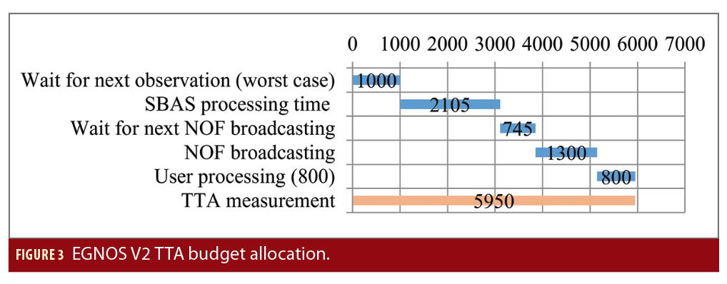
The European Geostationary Navigation Overlay Service (EGNOS) currently complies with the 6-second time to alert requirement compatible with Category I precision approach operations as defined in table 3.7.2.4.2-1 [1] (split into 5.2s for the SBAS system and 0.8s for the user display).
Early feedback from users indicates there may be an interest for future services offering a TTA budget smaller than the TTA budget of SBAS systems. The target for global TTA is between 1.5 and 5 seconds (allowing to achieve up to Category II approach TTA minima).
To prepare this evolution for further EGNOS versions, Thales Alenia Space has studied several evolutions to reduce the SBAS TTA. This study is system driven, identifying potential improvements at system level, for a reasonable increase of complexity.
A SBAS computes corrections and integrity data based on GNSS observations that are performed by the ground reference station network (named Receiver Integrity Monitoring Stations (RIMS) in EGNOS). In the context of a Dual Frequency Multi Constellation (DFMC) service, the observations contain the GNSS and SBAS navigation messages received and carrier-code, carrier-phase measurements on L1, L5 (for GPS) and E1, E5a (for Galileo) frequencies.
The SBAS also uses these observations to detect out of tolerance conditions.
The corrections, integrity data and alerts are then sent through SBAS messages using a GEO satellite. Observations are computed at RIMS level at 1Hz frequency, which corresponds to the frequency at which SBAS messages are broadcast.
Figure 1 provides a first level decomposition of the time to alert.
The “out of tolerance condition” is detectable from the SBAS using the next observations done at ground station level. Knowing the observations are performed at 1Hz frequency, the “waiting for next observation” time is between 0 and 1,000 ms (1,000 ms in worst case).
The SBAS processing time corresponds to the time needed by the system to process the observations, generate the corresponding NOF (Navigation Overlay Frame) message and prepare it for broadcasting.
The NOF message is then sent at the next GPS second. This generates a “waiting for next broadcasting in NOF” time. This time is between 0 and 1,000 ms.
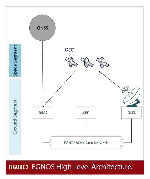
The SBAS processing time is spread over the SBAS systems. Figure 2 provides a high-level overview of the EGNOS V2 system.

The system is composed of the following subsystems:
• The Receiver Integrity Monitoring Stations (RIMS) that collect GNSS/GEO navigation messages and provide GNSS measurements to the Central Processing Facility (CPF).
• The CPF computes the complete navigation context, provides corrections and integrity data based on the data provided by RIMS and generates the NOF message to be broadcast
• The Navigation Land Earth Stations (NLES) that broadcast the NOF message to the GEO satellite
• The GEO satellite that broadcasts the NOF Signal In Space (SIS) to users
• The EGNOS Wide Area Network (EWAN) that is responsible for the data transmission from one subsystem to another
Each of the previously defined subsystems contribute to the SBAS processing time included in the time to alert.
Figure 3 gives the EGNOS V2 TTA budget allocation.
This article presents the optimizations axis for each part of TTA, except the user processing part that cannot be improved by the SBAS.
Optimization of SBAS Processing Time
The SBAS processing time is the part of TTA that is completely under SBAS responsibility.
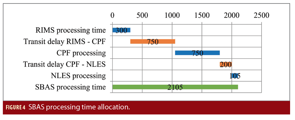
It is composed of observations processing at RIMS level, transmission of observations from RIMS to CPF through EWAN, CPF processing, transmission of NOF message from CPF to NLES through EWAN and NLES processing.
Figure 4 provides a high-level decomposition of SBAS processing time based on EGNOS V2 allocation.
An important part of the budget allocated to SBAS processing is dedicated to transit delay through EWAN (in orange in the previous graph).
The transit delays through EWAN constitute an important part of the TTA budget allocated to SBAS processing.
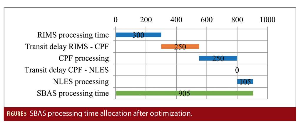
The collocation of CPF and NLES makes it possible to avoid transit delay between CPF and NLES. Based on EGNOS V2 allocation, this reduces SBAS processing time to 200 ms.
The transit delay between RIMS and CPF is mainly driven by the technology used for the link.
There are two types of RIMS sites:
• Wired RIMS. RIMS connected to a terrestrial access line.
• VSAT RIMS. RIMS connected to a Hub VSAT (a teleport) via a satellite link.
VSAT links are used on less than 25% of the RIMS sites on EGNOS V2.
Even if the RIMS to CPF maximum transit delay requirement is the same for both types, the observed transit delay is higher for VSAT than for Wired RIMS as shown in the next analysis.
Observation of transit delay on EGNOS V2 over a 11-day period gives the following results for all available VSAT RIMS and wired RIMS:
A solution without VSAT links reduces the allocated time to about 500 ms without the need for further technology improvement.
750 ms are allocated to CPF processing. The CPF is composed of two components:
• Processing Set (PS) that ensures the correction and integrity data and constructs the navigation message.
• Check Set (CS) that ensures the system integrity and verifies the generated messages.
Both components shall be analyzed. The CPF execution time is driven by the maximum execution time of both components and by the exchanges between PS and CS and with other subsystems like NLES. The exchanges are taken into account in the analysis.
Two axes of improvements have been studied: An update of hardware and algorithms with their scheduling improvements.
A previous analysis of PS algorithms (legacy and new algorithms) response time was performed using EGNOS V2 implementation, keeping the same algorithm sequencing and repartition over boards on a Linux Platform with a 3.5GHz CPU. Following this experimentation, 32 ms are theoretically needed per cycle to perform the computation of the latest V2 algorithms.
This leads us to consider an overall estimation of about 75 ms of total execution per cycle with a 1.5GHz CPU on nominal conditions (in single frequency context). Considering Dual Frequency Multi Constellation context (about 25% of additional computation time), about 25% of overhead for management of external interface (CS, NLES) and inter algorithm management, and an additional margin on about 30%, about 150 ms to 200 ms is needed for EGNOS V2 algorithms processing within the CPF allocated time.
Requirements for available CPU margins also have been considered. The analysis shows considerable margins exist in terms of CPU load to achieve a reduction of TTA budget for the Processing Set.
The analysis concludes a hardware composed of six boards with 1.5GHz CPU, reducing the CPF Procession Set execution time to 200 ms.
An equivalent analysis was performed with the CPF Check Set. The analysis was performed using EGNOS V2 implementation on a multi-board architecture based onVM6052 running at 2.2GHz.
This analysis concludes the processing time can be reduced to 200/300 ms.
In the context of DFMC, as part of the algorithms (inter frequency bias) are not needed, we can conclude that CPF processing time can be easily reduced to 250 ms.
In addition to EGNOS V2, Thales Alenia Space has developed its own Processing Set with a single board architecture (VM6052 running at 2.2GHz). By using SW partitioning, all algorithms can be scheduled on a single board with CPU margins compliant with resource consumption requirements (CPU is only used at 30% with a 2.2GHz processor).
Taking into account the CPU consumption on a single frequency implementation, and adaptation to DFMC (expandability factors for new constellation and non-required algorithms), the algorithms can be processed in less than 200 ms.
Taking into account these analysis, CPF processing can be reduced to 250 ms (4Hz).
Taking into account optimization of transit delays and CPF processing time, the SBAS processing time can be reduced to 905 ms as shown in Figure 5.

Optimization of waiting for next measurement time
As shown in Figure 1, part of the delay to alarm is due to the time elapsed between the “out of tolerance” event and the observation at RIMS level.
Several axes have been analyzed to reduce this time:
• Introduction of asynchronous processing. This makes it possible to detect “out of tolerance” events as soon as enough observations are available.
• Increase of RIMS output rate. Observations are performed more often at RIMS level, reducing the time between the “out of tolerance” event and the next observation.
Asynchronous Processing
In current EGNOS V2 implementation, observations are performed at the same time on all RIMS synchronized with GPS time. CPF algorithms are executed at 1Hz frequency as soon as almost all RIMS measurements are received.
In an asynchronous scheme, the RIMS produces measurements not synchronized with GPS time. The generation of measurements at the RIMS level would be done so the reception at CPF level would be uniformly distributed.
The analysis shows that for satellites with good observability (20 RIMS in view) 700 ms are required (with an acceptable probability) to detect “out of tolerance” events. Even with this optimistic hypothesis on satellite observability, the maximum TTA reduction obtained with asynchronous measurements is 300 ms.
Increase RIMS Output Rate
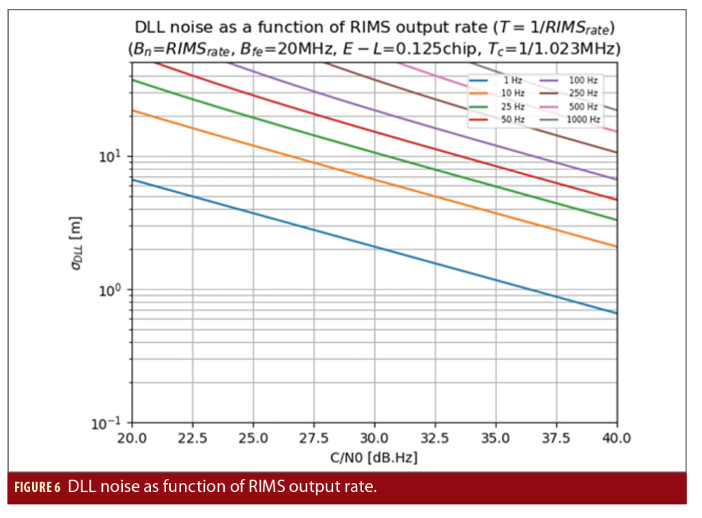
In this concept, all RIMS will generate raw measurements at the same time but with a frequency of higher than 1Hz. First, the quality of these measurements must be verified and the detectable “out of tolerance” events analyzed. Figure 6 shows adopting a frequency up to 10Hz loop bandwidth for the PR measurements (compared to the usual 1Hz) would not have a significant impact on processing performance.
To take advantage of the increased RIMS output rate, the CPF integrity check algorithms shall be executed at the same frequency. To be consistent with the computation capability studied at CPF level, the proposed frequency is 4Hz.
Taking into account the increased RIMS output rate of 4Hz and a CPF integrity check algorithm execution time of 250 ms, the SBAS message, including the alert, is ready to be broadcasted after 1,155 ms. Figure 7 shows the alert availability for broadcast.
The “waiting for next measurement” time is then reduced to 250 ms in the worst case, instead of the 1,000 ms for 1Hz measurement sampling. However, if the alerts are sent only through NOF with a 1Hz frequency, even if the system can detect alert conditions at a 4Hz frequency the alerts will be sent at 1Hz frequency. To take advantage of this improvement, the alerts shall be sent with the same frequency, 4Hz.
Optimization of waiting for next broadcasting and broadcasting time
The alerts are sent in the NOF, which is broadcast with a 1Hz frequency synchronized with GPS time.
This generates a delay up to 1 second. Note the NOF is broadcast over a period of 1 second. Users can decode the alarm only after the complete reception. A delay of 1 second shall be added to the TTA.
This delay (up to 2 seconds) is directly linked to the alarm broadcasting solution.
To reduce this time, an alternative solution “fast alert message” has been analyzed to broadcast the alarm to users.
The aim is to send alerts to the user as soon as possible without waiting for the next SBAS message broadcasting, which is done one time per second synchronized with GPS time.
Fast alert messages contain the alert flags (alarm/no alarm) for all satellites set in the PRN mask.
Management of fast alert messages implies a re-design of the user receiver that would require a MOPS standard update.
The user receiver shall consolidate the status of each satellite using both alert messages and NOF.
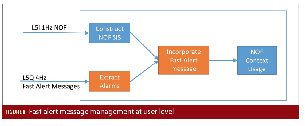
Figure 8 shows how the user receiver can incorporate fast alert messages to his NOF context.
“Construct NOF SIS” module constructs context using the NOF messages. After each alert message reception, the “extract alarms” module extracts the list of satellite alarms. The NOF context is then updated with the extracted alarms: a satellite is considered in alarm if an alarm is raised in fast alert message or in NOF SIS. The updated NOF context is then used like before.
Alarm hysteresis and repetition are ensured by the 1Hz chain in the NOF message.
There is no obligation to use the fast alert message for a receiver. There may be classes of users who can ignore the fast alert messages.

Fast Alert Message
SBAS alert messages, such as the Message Type 34, are transmitted today using a 250-bit long frame, including signalling and control fields (headers, CRC) at a transmission bit rate of 250 bits/s. As a consequence, a minimum 1-second latency is necessary to demodulate an alert message before processing the useful data. As an alternative, this article considers using the Q-component of the L1 and L5 frequency bands, with the strong assumption that the signal power available on the Q-component equals the I-component, without
taking into account that other potential services could be broadcast on the Q-channel in the future. To reduce the alert message duration, and hence the TTA, two complementary approaches are considered: a bit rate increase requiring alternative signal waveforms and a shortened frame, at least for alert message types.
An analysis of the bitrate increase approach is provided in [2], where several potential candidate signal waveforms were proposed. In [2], the use of Code Shift Keying (CSK) modulation is particularly emphasized and allows for reaching an increased bit rate up to a factor 4, i.e., 1 kbit/s. The CSK was used in conjunction with specially designed Low-Density Parity-Check (LDPC)
coding schemes within a Bit-Interleaved Coded Modulation, with Iterative Decoding (BICM-ID) architecture. The construction of GNSS waveforms bring additional arithmetical constraints on the sizes of LDPC uncoded words and coded words when taking into account the PRN sequence length, the number of code periods, and the size of the MT frame. In [2] the objective of the bit rate increase was reached, and the pros and cons of the candidate signals were proposed. However, using these alternative signals would constrain the alert message duration over 500 ms.
We preferred to use a more conservative approach, BPSK (because use of CSK would induce a heavy re-design of the receivers as it introduces a new modulation scheme) only as the Option 2B mentioned in [2], but with the perspective of a possible shorter alert message of 125 bits instead of 250 bits. It is foreseen that short-block LDPC codes have degraded performances with respect to larger block codes. Nevertheless, we envisaged to assess the Word Error Rate (WER) performance of an (125,250) LDPC code, concatenated with BPSK modulation, so as to enable 250 ms-latency alert messages. This proposal is presented in Table 2.
Some LDPC codes were proposed in an Experimental Specification published by CCSDS for short-block LDPC codes [3]. More specifically, we investigated the (128, 256) code and found a C/N0
performance of ~30.7 dBHz for a WER=10-3, which is quite a bit over the 30 dBHz target.
An alternative to the CCSDS codes was proposed in [4], and the new parity-check matrix by Medova in the (128, 256) code has shown a 0.5 dB improvement, reaching a WER=10-3 performance for a C/N0 of 30.25 dBHz, considered as an acceptable performance. Further improvements were also made to adapt the parity-check matrices to a (125, 250) code size without degradation of the C/N0 performance. Even better LDPC codes can be designed to reach the required 30 dBHz, opening the path to 250 ms latency (alert) messages and the necessity to construct a 125-bit long message.
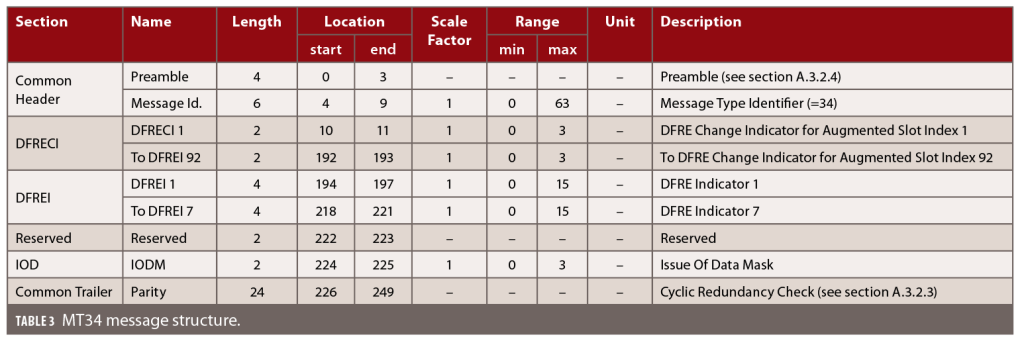
The new proposed message structure is based on MT34 from DFMC standard [5]. It is described in Table 3.
This message is used to transmit the Integrity Information through DFRECIs and DFREIs, for all the Augmented Slot Indices derived from the Satellite Mask. The payload is composed of 216 bits comprising: 92 DFRECIs (Change indicators), 7 DFREIs, Issue of Data Mask (IODM), 2 additional bits are reserved. The signalling and control (overhead) are composed of 34 bits: a preamble field, a Message Type ID field, and a Cyclic Redundancy Check (CRC) of 24 bits.
In the context of a shortened version of integrity information, we assume it shall have the lowest impact on other existing message types already transmitted on the I-component. This implies the satellite mask (MT 31), allowing to set up to 92 satellites, is maintained in its current definition. Hence, our main objective is to obtain a minimal alert information (1 bit for alert flag) for all 92 satellites within a total of 125 bits, which leaves only 33 bits.
After taking into account the IODM using 2 bits, the Message Type ID field over 6 bits, and the preamble over 4 bits, there remains only 21 bits for CRC. The standard CRC-24Q currently used in EGNOS is thus too long for this new potential framing. However, because the message frame length also has decreased, the choice for a shorter CRC was proposed. Our study shows it is possible to reduce the number of bits for the CRC with equivalent bit protection level (Hamming Distance), or without loss of integrity by replacing the CRC-24Q with a CRC-16 (0x9EB2).
Finally, we propose a new 125-bit message structure in Table 4 using a well performing CRC-16, as described in Table 3, compatible with the candidate signal Option 2D at either Rb=250 bits/s (500ms latency) or Rb=500 bits/s (250ms latency).


Fast Alert Message Broadcast
To shorten the “waiting for next broadcasting” time, the fast alert message can be sent as soon as an alert is available. However, if alert detection is based on 4Hz RIMS measurements, the fast alert message broadcasting can be done with a 4Hz frequency synchronized with alert availability at CPF output.
Fast alert message insertion makes it possible to eliminate the « waiting for next broadcasting » and to reduce the broadcasting time to 250 ms. The global delay is 500 ms instead of 2 s.
Conclusion
This article identifies several options to improve the TTA for SBAS.
It defines a first level of improvement that avoids any modification of the SBAS user standard and considers the benefit of optimizing CPF processing along with using measurements coming from wired RIMS only and/or additional RIMS measurements. These features allow us to reach a 4 second target compared with the current 6 second budget.
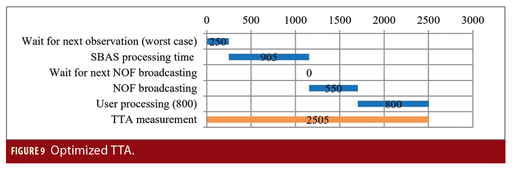
A second level of improvement is obtained with a modification of the standard and the introduction of fast alert messages. Fast alert messages are broadcasted using the SBAS Q-channel and backward compatibility is maintained (Fast Alert messages could be ignored). This way, a target close to 2.5 seconds is met, as depicted in Figure 9. More details can be found in [6].
Acknowledgements
This work has been performed and funded under a contract of the European Space Agency in the frame of the EU Horizon 2020 Framework Program for Research and Innovation in Satellite Navigation.
Disclaimer
The views presented represent the authors’ opinions. They should be considered R&D results and not taken to reflect the official opinion of the EU and/or the European Space Agency, in particular for what relates to present and future EGNOS system designs.
References
(1) ICAO SARPs Annex 10 Volume 1 amendment 9
(2) Axel Javier Garcia Peña, Rémi Chauvat, Christophe Macabiau, Jaron Samson, Ivan Lapin, et al., Potential candidates for new SBAS signals. PLANS 2020 IEEE/ION Position, Location and Navigation Symposium, Apr 2020, Portland, United States
(3) CCSDS 231.1-O-1Short Block Length LDPC Codes for TC Synchronization and Channel Coding. Experimental Specification. Issue 1. Recommendation for Space Data System Standards (Orange Book)Book), CCSDS 231.1-O-1, Washington, D.C.: CCSDS, April 2015.
(4) L. R. Medova, P. S. Rybin and I. V. Filatov, “Short Length LDPC Code-Candidate for Satellite Control Channel,” 2018 Engineering and Telecommunication (EnT-MIPT), Moscow, Russia, 2018, pp. 163-166, doi: 10.1109/EnT-MIPT.2018.00044.
(5) ED259A (draft 21-06-2023) MOPS for Galileo/GPS/SBAS airborne equipment
(6) C. Renazé, C. Bourga, M. Clergeaud Thales Alenia Space, Toulouse, France, J. Samson ESA. Reduction of system time to alert on SBAS. NAVITEC 2022
Authors
Céline Renazé is a specialist in safety architecture at the Algorithms Design and Performance department of Navigation Domain, Thales Alenia Space. She received her M.S. in software engineering from the Paul Sabatier University, Toulouse, France, in 2003. She currently works on SBAS ASECNA as a System Architect.
Christophe Bourga is the head of the Navigation Systems Architecture department at Thales Alenia Space. Since 1997, he has worked on various topics in the navigation domain: GNSS mission, payload design, Galileo signal, formation flying, Galileo algorithms and performance, EGNOS architecture and evolutions, and ARAIM.
Matthieu Clergeaud is a system engineer at the Radionavigation department at Thales Alenia Space. He received his Engineering degree in Space Communications Systems from Telecom INT (Institut National des Télécommunications) in 2003. He now works on EGNOS-related projects.
Jaron Samson works as a Navigation Engineer at ESA’s Technical Centre (ESTEC) and has been involved in EGNOS, GNSS Evolutions, and R&D related to navigation. From 2012 until 2021 he worked as a System Engineer at ESA’s EGNOS Project Office in Toulouse, France. Jaron holds an M.Sc-degree in Physical and Mathematical Geodesy from the Delft University of Technology, The Netherlands.


