In today’s world of GNSS-contested environments and the emergence of multi-sensor fusion capabilities, there is a demand for filters that can navigate without the aid of GNSS. This article evaluates a complementary navigation filter designed to steer a sUAS autopilot in GNSS-contested environments.
ANDREW APPLEGET, JOSIAH WATSON, JEREMY GRAY, CLARK TAYLOR, AIR FORCE INSTITUTE OF TECHNOLOGY
Global Navigation Satellite Systems (GNSS) have been the standard source of positioning and timing for a multitude of applications leading to an over-reliance on its capabilities and a notable reduction in performance or interoperability when it is unavailable. The emerging threats to satellite navigation, and to the Global Positioning System (GPS) in particular, necessitate the development of modular navigation architectures that can use complementary methods (e.g. vision, signals of opportunity, magnetic anomalies) alongside or in the absence of GNSS.
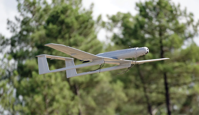
In general, this research strives to develop a modular navigation and autonomy test bed on a small unmanned aerial system (sUAS) to develop, refine and examine the intersection of these fields as well as demonstrate cutting-edge research through real-world flight tests. This article describes the development of this test bed [1] and the results of a flight test during the 2021 Position, Navigation and Timing Assessment Exercise (PNTAX) at White Sands Missile Range (WSMR) where real-world GNSS signals were
contested and denied. An Extended Kalman Filter (EKF) fused the complementary sensor payload and provided GNSS-denied state estimates to the autopilot for autonomous flight. Two successful hour-long flights were achieved during which no GNSS measurements were available.
Navigation Test Bed
To develop a modular navigation and autonomy test bed on sUAS, there are several components that must be developed, including (a) an estimation filter for combining complementary sensors together, (b) a software architecture that enables different sensors to be added with minimal modifications, (c) complementary sensors to enable navigation, including ranging radios, GNSS and IMU, an IR camera with map matching algorithms, and a barometer, (d) error models for each sensor, (e) avionics integration for flying the aircraft in GPS-denied environments, and (f) the airframe itself.
Modular Open Systems Approach (MOSA)
One of the primary objectives of this research is to develop a reusable test bed for future research. This concept demands constant modification of components and software, which can be accomplished by adopting MOSA and using components designed with this in mind. MOSA relies on clearly defined interfaces between system components, which allows any implementation that meets these interface requirements to be “plugged into” that system component slot.
In recent years, the Autonomy and Navigation Technology (ANT) Center at the Air Force Institute of Technology (AFIT) developed a modular estimation library named scorpion. This concept was taken over by IS4S, who redeveloped it into the C++/Python Navigation Toolkit (NavTK) library, which was used for this research.
Due to the number of software components and the aim of modularity, a common message format and transport layer were used. The All Source Positioning and Navigation (ASPN) version 2.2 message standard was used for all navigation messages, which were serialized and transported using Lightweight Communications and Marshalling (LCM) [3]. For each sensor, a driver was developed to convert the sensor’s propriety data format to ASPN and publish it to the LCM network bus.
An image pre-processor used the published infrared (IR) images to generate and publish a position estimate. The filter code unpacked the transmitted ASPN-LCM measurements and converted them to the ASPN-Python classes supported by the NavTK filter. The filter estimate was published over LCM for use by the autopilot via its driver.
LCM uses a publish/subscribe pattern to communicate across a network bus, thus any data that came across this bus could be easily logged for later processing. In addition, using a common message format meant the applications could be containerized as long as they could communicate across the network. Using this communication schema enabled the modular design of the system, which was demonstrated by the ease of integrating new components when they became available.
Software Development and Deployment Infrastructure
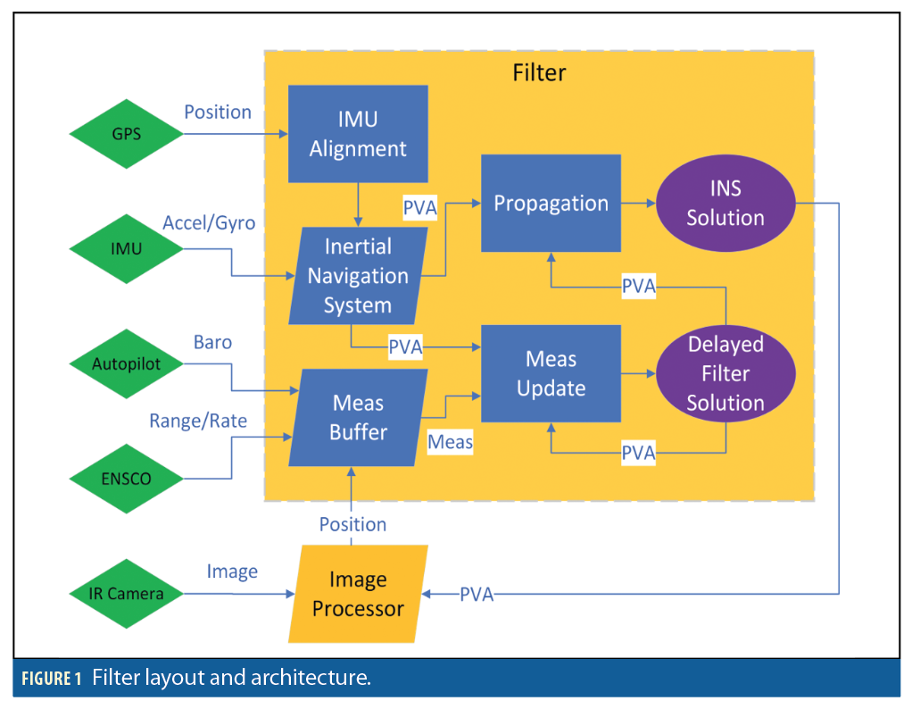
To navigate without GNSS signals, this research required many different sensors, each with proprietary commands and data formats. In addition, integrating code from multiple developers and using different CPU architectures for development (x86_64) and deployment (Advanced RISC Machine (ARM)-64) meant that a modular approach was needed to manage this complexity. Figure 1 depicts the layout and architecture of the filter platform used on the aircraft.
Each software component was developed and deployed inside a separate virtual container to manage the differing dependencies and versions. Virtual containers are similar to virtual machines in that each create an isolated environment that allows applications to be installed and run on the same physical hardware without interfering with one another. However, containers only create a separate file system, not a separate operating system kernel, making them faster and smaller in size than virtual machines.
Using individual containers for each component had many tangible benefits. First, the development environment was consistent over time and could be easily installed and used on other devices. This greatly reduced the amount of troubleshooting required during development and system integration. Next, because each of the components were deployed in containers, they could be easily added to or moved between the payload’s two Nvidia Jetson Xavier NX computers (e.g. to balance CPU load). Finally, using containers allowed the code to be developed on x86_64 based laptops and easily deployed to the ARM-based payload computers. This research used Docker Community Edition to create and manage containers. A combination of Docker Compose and Linux’s System Daemon (systemd) services were used to selectively run the components during flight testing.
The filter code was primarily developed in Python using the NavTK library. The script consisted of NavTK class objects to model an Extended Kalman Filter (EKF) with states, measurements and the filter engine itself. The library mechanized the inertial measurements to produce a trajectory that was then corrected with measurements from other sensors.
This research added a measurement buffer to receive messages via LCM, prepare them for the filter, and re-order them based on the measurement time. The filter was configured to lag behind the current time, which allowed the measurement buffer to handle messages that were received out of order. When a new measurement was ready, it was requested by the filter engine, which dispatched it to the appropriate measurement processor to perform an update. The filter state was then requested and published to the LCM bus at a constant rate to be consumed by the autopilot.
The filter used the Pinson 15-state error model detailed by Titterton & Weston [4], which includes position, velocity, tilt, acceleration bias, and attitude bias, each in three axes. The Pinson 15 error states were initialized to 0, while the filter trajectory (i.e., “whole states”) for position, velocity and attitude (PVA)was initialized to the first PVA value produced by the NovAtel PwkPak7
receiver after it had successfully aligned. In essence, the trajectory of the filter was initialized to the truth PVA when the filter began operation.
Clock
Proper timing in a navigation system is critical to successfully fuse the sensor information with the filter. Time stamping measurements incorrectly can lead to decreased performance and added complexity when aligning measurements later, either in the filter or during post-processing. Ideally, each measurement would be timestamped when it is collected by the sensor, but many sensors do not have that capability. For all of the sensors flown, the best timestamp available was the computer’s system time when the measurement arrived at the driver. For this platform, a TM2000B Time Machine GPS NTP/PTP network time server was used to synchronize each computer’s system time with its internal clock disciplined by GPS. This ensured the sensor messages were timestamped by a common clock.
Ranging Radio
The navigation platform was equipped with an ENSCO TCR-D 421 ranging radio. These devices use radio signals to communicate with one another and determine their relative distance. The maximum effective range is listed as 1,000 m with RF line of sight (LOS), while the ranging accuracy is listed as 50 to 500 cm in tactical environments Additionally, the radios can obtain measurements via accumulated Doppler known as carrier phase velocity or range-rate measurements. The radios operate at a carrier frequency of 5.8 GHz, outside the L-band used by GNSS signals.
In addition to the ranging radio in the navigation platform, three other ENSCO ranging radios were placed on the ground near the flight region. The ranging radios were positioned to allow for the best geometry and minimize failed measurement acquisitions.
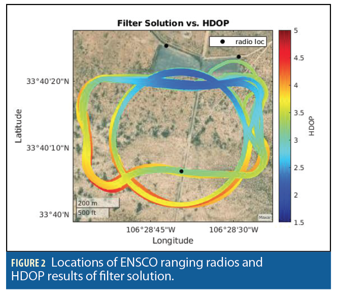
The radio antennas, designed as omnidirectional antennas, were oriented at a 45° angle so as to point a line perpendicular to the midpoint of the antenna toward the majority of the aircraft’s intended flight path. This was because the midpoint is the estimated maximum of the radiation pattern (approximately 5 dBi). In other words, the radio antennas were positioned as if they were ideal dipole antennas. The geometric positions of the ground radios are depicted on a satellite map in Figure 2.
To ensure accurate measurement updates for the range and range-rate measurements, the static positions of the ground radios needed to be accurate to less than one meter. To achieve this level of accuracy, GPS data was collected and sent to the Online Positioning User Service (OPUS) website [5] to get a surveyed position. The three radio locations are depicted in Figure 2.
The radios were positioned in a triangle inside the flight envelope to minimize the Horizontal Dilution of Precision (HDOP) (depicted in Figure 2).
Each ENSCO radio is numbered by the manufacturer and is also used to distinguish each radio in this analysis.
GNSS and IMU
The NovAtel PwkPak7 receiver integrates both a GNSS and an IMU into one unit. In addition to providing GNSS measurements from multiple satellite constellations, this unit is capable of providing IMU measurements at a rate of 200 Hz.
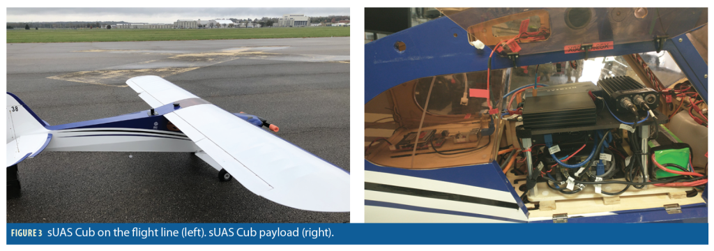
This receiver was used in conjunction with a Maxtena M8 L1/L2/L5 GNSS antenna mounted on top of the aircraft with a ground plane (Figure 3). The receiver is capable of processing measurements from GPS, GLONASS, Galileo and BeiDou signals including the modernized GPS and GLONASS signals. The NovAtel receiver can be programmed to provide both satellite-only position measurements for loosely-coupled filters or pseudorange measurements for tightly-coupled filters. In addition, the receiver provides its own tightly-coupled solution via an integrated GNSS-inertial filter. The filter in this research did not process any satellite measurements, but the tightly-coupled PVA measurements collected from the NovAtel receiver during the benign period were later used as truth data to analyze the filter performance.
IR Camera and Map Matching
The Teledyne FLIR Boson 640 IR camera was fixed to the plane facing directly downward toward the ground when the aircraft was flying level. The IR image data was processed using a vision
algorithm developed by Veth Research Associates, LLC (VRA) and based upon research in [6] and [7]. The algorithm used an IR image and a current position estimate from the filter to produce a new position estimate. It did this by comparing the current image with a database of satellite images provided a priori. The position solution calculated by the vision algorithm was fed back to the filter to update its overall trajectory.
Barometer
The barometer was one of the Pixhawk autopilot’s internal sensors. The Pixhawk was connected via USB to a payload computer running an LCM driver reading and publishing on two separate channels for absolute pressure and temperature measurements. The measurement buffer subscribed to both of these LCM message channels. As temperature measurements were received they would be stored as the current temperature. As absolute pressure measurements were received they would be used along with the current temperature to calculate an altitude measurement via a standard atmospheric model. The altitude measurement was then passed to the filter script, which dispatched the data to the appropriate measurement processor to update the filter’s altitude state.
Filter and Sensor
Error Modeling Parameters
The sUAS Cub aircraft consisted of two primary systems: the navigation payload and the avionics system. The navigation payload included the navigation sensors and a computer used to interface with sensors and fuse sensor measurements using NavTK.
The filter IMU parameters were modeled using a Pinson 15 error model. The inertial drift parameters had to be inflated from the values depicted on the datasheet to account for airframe vibrations. In addition to the Pinson 15 states, the barometer had a bias that was modeled as a First-Order Gauss-Markov (FOGM) state. The sensor measurement errors were modeled as zero-mean Additive White Gaussian Noise (AWGN).
In addition to the IMU error model, the error parameters for individual sensors were intentionally chosen to be larger than what was published in datasheets or experienced in the flight tests. This was implemented to mitigate possible anomalies that may have occurred with the sensors, leading to large errors. Raising the uncertainty can help mitigate this when using EKFs. Additionally, large residuals (i.e. residuals compared to what the filter was expecting) could potentially break a filter running in real time.
Avionics and External Navigation Integration
The avionics system consisted of a Pixhawk 2 autopilot running ArduPilot firmware with internal sensors including an IMU, compass, baro-altimeter, external GNSS, and airspeed sensors. During typical non-contested operations, the autopilot performs sensor fusion via its EKF to provide states to its control system for autonomous waypoint following. If GNSS is contested, the autopilot does not have a source for position information and will become increasingly more uncertain about its horizontal position, meaning an external navigation solution would need to be provided. The problem then is determining how to inject a navigation solution into an autopilot not designed to take complementary navigation inputs.
There were three possible solutions to this problem. The most intuitive solution was to circumvent the autopilot navigation filter and provide the NavTK filter states directly to the controller. This would require the calculation of additional filter states, significant rework of the autopilot firmware, and additional effort to obtain flight approvals. The second solution was to encode the filter states as a GPS L1 signal using a Jackson Labs GNSS transcoder. This solution is more elegant and easier to integrate into existing systems, however at the time of this research this technology was not ready for use. The solution that was implemented was to encode the filter states as a National Marine Electronics Association (NMEA) message and send it via serial connection to the autopilot’s external GNSS receiver port. This stand-in for an external GNSS receiver enabled the autopilot to update its EKF based on the external filter states.
A consideration when developing this method was to investigate the effects of injecting the external filter solution into the Pixhawk filter that is expecting a GNSS measurement. The ArduPilot firmware can be run as a software-in-the-loop (SITL) simulation that is identical to the firmware flown with a physics simulator. A test was conducted using the SITL simulation to see the effects of AWGN to the GPS input. To accomplish this, the truth from the physics simulation was programmatically acquired, corrupted, then injected back into the autopilot. The autopilot, with proper configuration, was resilient to noise orders of magnitude larger than that expected by our navigation system.
The proposed injection method also introduces latency from sensor acquisition to solution injection on the order of 100ms to 200ms. The autopilot expects and can accommodate latency with a simple parameter change, however, it does expect the measurement at a constant rate. To accommodate this in addition to slower processes like the image position solution, the filter was designed to provide a 500ms delayed solution at a constant rate of 10 Hz.
Airframe
The payload and avionics were integrated on a hobbyist one-third-scale Cub. The loiter time, using a gas engine and batteries for the electronics, was 75 minutes. Figure 3 depicts the sUAS airframe and integrated payload.
Data Collection and Flight Plan
The flight test and data collection were conducted at WSMR during the 2021 PNTAX test event. Between each of the jamming scenarios, there were benign periods when GNSS signals were available and uncontested. Throughout the duration of the flight, the computer on the aircraft recorded both the measurements from individual sensors as well as the overall filter solution at a given timestamp.
Flight Testing During Contested GNSS
Testing and demonstration provide additional challenges when developing complementary navigation systems. It seems trivial to say the system is not using GNSS if there are no GNSS measurements used in the filter. However, reliance on GNSS runs so deep that its use can unintentionally emerge, thus a real-world contested environment is needed to truly evaluate how a system operates without GNSS.
One difficult reliance to overcome is how to produce a truth source that would typically be provided by a GNSS receiver. To accomplish this, each flight had two phases; a benign period, without interference, and the contested period when GNSS jamming waveforms were broadcast. During both periods, the autopilot followed the same loiter and a box pattern as a simple truth source. During the contested period, the filter’s overall performance was compared against the tightly coupled GNSS-inertial solution for truth. The filter estimates were assessed via nine different states: PVA, each with three degrees of freedom. During the interference period, due to the unavailability of GNSS signals, the filter performance may be indirectly assessed by observing the residuals of its sensors, namely, the ranging radios, and by examining the ground traces maintained by the autopilot.
Commonly overlooked as being reliant on GNSS, inertial alignment procedures are critical to all navigation systems to provide the filter with the initial position and orientation of the IMU in the navigation frame. The IMU used was not sufficiently sensitive to detect the Earth’s rotation and thus required a dynamic alignment. In the absence of coarse dynamic alignment algorithms in NavTK at the time of the flight test (this capability has since been added), the aforementioned receiver’s own algorithm was relied upon to send an alignment flag to the filter script via a separate LCM message. The receiver required GNSS signals to obtain a successful alignment, thus the dynamic alignment was performed during the benign period.
Another commonly GNSS-reliant component is the timing system, which frequently requires GNSS to discipline its clocks. During the contested period, the Time Machine was not disciplined by GPS, allowing it to coast using its internal oscillator. Lab tests performed before the live event revealed the time machine was able to coast without GPS and maintain a sufficiently stable time without a significant drift for our application, with the same behavior observed during the flight test after the hour-long GPS outages.
The last, and likely most vital, consideration when performing these flight tests without GNSS was safety. Flight testing on an unmanned aircraft versus a manned aircraft presents different challenges. For the manned aircraft, the pilot maintains constant control from the cockpit and is able to more easily observe the aircraft’s attitude and position through various avionics and external sensing sources, in addition to visual observation when weather allows. A safety pilot on the ground operates the sUAS, which makes knowing the attitude difficult in some relative positions. The sUAS Ground Control Station (GCS) operator only knows as much as the telemetry from the autopilot provides and does not have access to the same external positioning sources as manned aircraft pilots. If the vehicle flies beyond visual line of sight (BVLOS), the safety pilot cannot fly it.
Similarly, if the telemetry radio becomes degraded because of interference or range, the GCS operator can no longer command the aircraft. To compound the issues, the fail-safes used by the autopilot to navigate back to a rally point for recovery are no longer available if GNSS is contested, thus forcing the autopilot to perform dead reckoning. To mitigate these issues, the vehicle was never flown BVLOS of the safety pilot for quick manual recoveries. Further, the telemetries from both the autopilot and navigation payload were used for human-in-the-loop integrity monitoring. Finally, a build-up of objectives was performed from least risky to most risky, starting with safety pilot manual flights for system verification and building up to a fully autonomous flight without GNSS.
Results
The following analysis consists of two parts, one for each scenario: the benign period before and the contested period during the jamming scenario. Given the truth data at a given time, along with the surveyed ENSCO radio positions, the truth ranges may be calculated to compare the ENSCO radio measurements against the truth ranges to evaluate the performance of the ENSCO radio. Additionally, because the vision-camera algorithm calculates the position at a given time, it may be compared against the truth as well [8].
During the jamming scenario, as previously mentioned, measurement residuals (i.e., the difference between the estimated measurement based upon the filter solution, and the actual measurement) can be used to determine filter performance in the absence of truth, assuming their performance remains consistent throughout the duration of the flight. The residual measurements of the ranging radios were used to assess the accuracy of the filter solution in the absence of truth. Thus, if the residual measurements do not vary across the dataset, it stands to reason that the filter performance did not change.
The sUAS flew two primary flight patterns: a circular loiter pattern and a box-shaped pattern determined by four waypoints. With the exception of take-off and landing, the aircraft was set to fly in autopilot mode. Additionally, the aircraft flew at three different altitudes (approximately 500, then 600, then 400 m) while it was in autopilot mode, for given amounts of time.
Benign Performance
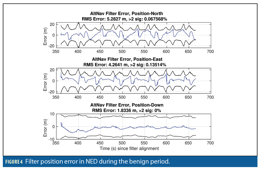
During the benign period, the filter solution was compared against the truth data from the NovAtel receiver’s tightly-coupled solution, linearly interpolated to the time of the filter solutions. Figure 4
depicts the filter error from the time of first alignment to the beginning of the jamming scenario. The filter error was compared against its 2σ covariance bound.
During the steady-state period (350 seconds after takeoff), the filter position error appeared to remain within the 2σ bound for more than 95% of the time as expected for a Gaussian error distribution. The Distance Root Mean Square (RMS) horizontal error of the filter was 6.79 m, while the RMS vertical error was 1.83 m.
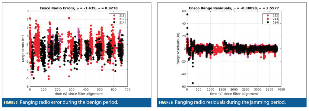
To assess the accuracy of the filter during the contested period, the measurement error residuals of the ranging radios must first be characterized. The ranging radios were evaluated on the basis of the truth position interpolated to the time the radio measurements were made. The Root Sum Square (RSS) range from the surveyed radios to the truth position is considered the truth range, while the difference between the measurement range and the truth range is considered the range error. The calculated range error is depicted in Figure 5.
The ENSCO radios appeared to be accurate to within approximately 5 m. Although combining the IR camera and the map-based positioning algorithm helped constrain the filter trajectory from drifting from the truth, the ranging radio measurements contributed as well. All three radios appeared to perform consistently with each other. The residuals are larger than expected (based on the sensor specifications) due to the dynamics and vibrations of the aircraft coupled with ground multi-path. The 2σ error appeared to be within approximately 2 m.
Performance During Jamming Scenario
During the jamming scenario, the NovAtel receiver was unable to maintain a solution due to GNSS signals being strongly contested. Consequently, there is no truth data with which to compare the filter solution. There are two main contributing factors to measurement residuals: the filter solution and the measurement itself. If the error distributions of the measurements are assumed to remain consistent, it is reasonable to indirectly assess the filter performance via the measurement residuals in the absence of truth data. The error characterization of the previous section can be used to determine the filter performance during the contested period when no truth data from the receiver is available. Therefore, one can evaluate the range residuals of the radios to determine if the filter solution deviates during the jamming scenario because the radio frequency of 5.8 GHz was not jammed during the exercise. As depicted in Figure 5, the accuracy of the ranging radios is within 5 m. Figure 6 depicts the residuals of the ENSCO radio measurements throughout the duration of the data collection, including both the benign and contested periods.
The time depicted in Figure 6 is the time elapsed since the NovAtel receiver was aligned during the benign period. Aside from the beginning of the data collection, where there are a few large outliers, the residuals appeared to be consistent with a 2σ value of approximately 5.12 m, along with a small bias. The larger residuals at the beginning of the data collection can be attributed to the dynamics associated with the aircraft taking off in manual mode and maneuvering to get to the correct altitude and begin executing its flight plan. Once the aircraft was cruising at a constant altitude and operating on a given flight path in autopilot mode, the residuals improved to a tighter distribution.
From observation of this data, it can be concluded, with a 95% confidence, assuming the error distribution of the ranging radios’ measurements remains consistent, that the filter during the jamming performed to within a 11 m error budget.
These values are derived from the maximum measurement error of 5 m observed for the radio measurements during the benign period and a 2σ value of 6 m for the measurement residuals of the radio ranges during the steady-state phase of the flight. Additionally, the aircraft did not visibly deviate from the flight plan during the duration of the flight.
Conclusions and Future Work
This research demonstrates that in the absence of GNSS navigation, a complementary navigation solution can be used to steer sUAS via a closed control loop in an unmodified commercial off-the-shelf (COTS) autopilot. With 95% confidence, the overall filter solution did not drift by more than 11 m, constraining the overall filter solution.
These results will help reduce existing limitations and inform future decisions and techniques for flight testing in contested environments. In the future, the ANT Center plans to extend the range to BVLOS, where sensor performance and consistency, along with a reliable return to base function, is critical to prevent loss of the aircraft. Extending the range will allow for more realistic missions and the ability to pick up low frequency magnetic anomaly signals. Additionally, the use of non-contested GNSS signals will be evaluated for use as a truth solution and backup navigation source when in contested environments.
The ANT Center also plans to add and refine the existing sensor load-out to include magnetometers for magnetic anomaly navigation, using a more operationally representative ranging capability, laser altimeter terrain map-matching, and an IMU capable of static alignment to reduce the reliance on GNSS signals. The use of Software Defined Radio (SDR) GNSS receivers is being investigated to extend the use of GNSS further into jamming. Integrity may be improved through the use of integrity assurance techniques such as Autonomous and Resilient Management of All-Source Sensors (ARMAS) [8] to determine faulty measurement sensors.
The intersection of autonomy and navigation is also part of the ANT Center’s future road map, along with plans to further develop and assess path-finding algorithms [9] that optimize navigational performance. Further efforts are being made to adopt community MOSA products. As such, the ANT Center plans to integrate its filter with Position, Navigation and Timing Operating System (pntOS) and make its system ASPN2023 compliant. Finally, the ANT Center is continuously refining its development process and is now beginning to develop and use a modular sensor simulation library to aid in evaluating sensors before flying and plan to use real flight data to verify and improve sensor measurement models.
Acknowledgments
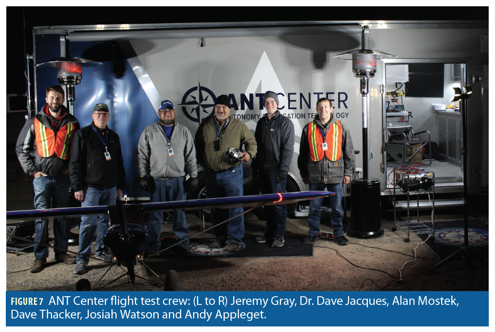
The authors would like to acknowledge Dr. Dave Jacques, Dave Thacker and Alan Mostek of the ANT Center for their contributions to preparing the aircraft and executing the flight tests, and support by our collaborative partners from ENSCO, VRA and IS4S that made this research possible.
This article is based on material presented in a technical paper at ION GNSS+ 2022, available at ion.org/publications/order-publications.cfm.
References
[1] A. Appleget, J. Watson, J. Gray, and R. C. Leishman, “Evaluation of a complementary navigation filter
steering a uas autopilot in a gnss contested environment,” in Proceedings of the 35th International
Technical Meeting of the Satellite Division of The Institute of Navigation (ION GNSS+ 2022), Denver, CO,
September 2022.
[2] K. Kauffman, D. Marietta, J. Raquet, D. Carson, R. C. Leishman, A. Canciani, A. Schofield, and M.
Caporellie, “Scorpion: A modular sensor fusion approach for complementary navigation sensors,” in
2020 IEEE/ION Position, Location and Navigation Symposium (PLANS), Portland, OR, April 2020.
[3] A. S. Huang, E. Olson, and D. C. Moore, “Lcm: Lightweight communications and marshalling,” in 2010
IEEE/RSJ International Conference on Intelligent Robots and Systems, Taipei, Taiwan, Oct 2010, pp.
4057–4062.
[4] D. Titterton and J. Weston, Strapdown Inertial Navigation Technology. London: Institution of
Engineering and Technology, 2004.
[5] National Geodetic Survey, “Opus: Online positioning user service,” January 2022. [Online]. Available:
https://geodesy.noaa.gov/OPUS/
[6] T. Machin, J. Raquet, D. Jacques, and D. Venable, “Real-time implementation of vision-aided
navigation for small fixedwing unmanned aerial systems,” in Proceedings of the 29th International
Technical Meeting of the Satellite Division of The Institute of Navigation (ION GNSS+ 2016), Portland,
OR, September 2016, pp. 1305–1311.
[7] D. T. Venable, “Improving real-world performance of vision aided navigation in a flight environment,”
Ph.D. dissertation, Air Force Institute of Technology, September 2016.
[8] A. Appleget, R. Leishman, and J. Gipson, “Evaluation of sensor-agnostic all-source residual monitoring
for navigation,” in Proceedings of the 2021 International Technical Meeting of The Institute of
Navigation, January 2021, pp. 339–353. [Online]. Available: https://doi.org/10.33012/2021.17837
[9] T. I. Machin and R. C. Leishman, “Implementation of the rapidly-exploring random belief tree and
statistical analysis of functionality,” in 2022 International Conference on Unmanned Aircraft Systems
(ICUAS), 2022, pp. 427–433.
Authors
Andrew Appleget is a Research Engineer at the Autonomy and Navigation Technology (ANT) Center at the Air Force Institute of Technology (AFIT). He has a B.S. in Electrical Engineering from Northern Illinois University and an M.S. in Electrical Engineering from Ohio University. His research interests include navigation by Low Earth Orbit (LEO), Doppler signals and navigation integrity.
Josiah Watson is a Research Engineer and currently the DevOps Lead at the ANT Center at AFIT. He has a B.S. in Computer Engineering from Cedarville University and an M.S. in Electrical Engineering from AFIT. His research interests include indoor and vision-based navigation, machine learning and artificial intelligence.
Jeremy Gray is currently the Research Engineering Team Lead at AFIT’s ANT Center. He earned a B.S. in Mechanical Engineering Technology from the University of Dayton and an M.S. in Systems Engineering from AFIT. His research interests include complementary navigation systems, simulation, autonomous systems and sUAS flight testing.
Dr. Clark Taylor is Director of the ANT Center at AFIT and an Assistant Professor of Electrical Engineering. He earned his B.S. and M.S. degrees from Brigham Young University and his Ph.D. in Electrical Engineering from UC San Diego. His research interests include vision-aided navigation, distributed estimation and error estimation.


