Existing methods for improving the GNSS performance commonly attempt to enhance the signal processing and navigation estimation parts of a single receiver. Such approaches, however, leave unexplored the potential benefits inherent to the integration of data from multiple receivers.
Existing methods for improving the GNSS performance commonly attempt to enhance the signal processing and navigation estimation parts of a single receiver. Such approaches, however, leave unexplored the potential benefits inherent to the integration of data from multiple receivers.
This article introduces the concept of a MUlti-platform Signal and Trajectory Estimation Receiver (MUSTER) and demonstrates its technical feasibility using experimental data. MUSTER uses collaborative GNSS where individual (non-collocated and asynchronous) receivers/nodes exchange their signal and measurement data in order to enhance GNSS navigation capabilities in degraded signal environments, such as urban canyons and indoors.
In the article, we will specifically address the use of collaborative receiver architecture for tracking of weak signals and describe algorithmic approaches that are validated with experimental data.
MUSTERing Cooperation
MUSTER organizes individual receiver nodes into a collaborative network in order to enable:
1) integration at the signal processing level, including:
- multi-platform signal tracking for processing of attenuated satellite signals
- multi-platform phased arrays for electronic support (ES) and electronic protection (EP)
2) integration at the measurement level, including:
- joint estimation of the receiver trajectory states (position, velocity, and time)
- multi-platform integrity monitoring via detection and identification of measurement failures.
To exclude a single point of failure, the receiver network is implemented in a decentralized fashion. Each receiver obtains GNSS signals and signal measurements (code phase, Doppler shift, and carrier phase) from other receivers via a communication link. A receiver then uses these data to operate in a MUSTER mode (i.e., to implement a multi-platform signal fusion and navigation solution). At the same time, each receiver supplies other receivers in the network with its signal and measurement data.
The efforts described here focus on the use of MUSTER for multi-platform tracking of weak GPS signals. The tracking architecture was developed to integrate signals from multiple independently operating GPS receivers (including independent clock operations) in order to improve the signal-to-noise ratio (SNR) and enable processing of weak signals.
This technological approach is specifically tailored towards extending the GPS navigation envelope into extremely challenging environments. We can envision many applications of the MUSTER, for example, indoor localization for search and rescue purposes and collaborative signal recovery with cellular phone users in order to enable location-based services (LBS) for indoor areas as shown in Figure 1.
The key benefit of the technology is that the SNR can always be improved by increasing the number of receiver nodes. In other words, GPS navigation can always be brought further indoors by adding new users to the collaborative network.
The MUSTER signal processing approach extends to networked GPS receivers an open-loop tracking concept previously researched for single receivers (see the article by van Graas et alia listed in the Additional Resources section near the end of this article).
This method combines signals from multiple platforms to construct a joint three-dimensional (3D) signal image (signal energy versus code phase and Doppler shift). Signal parameters (code phase, Doppler shift, carrier phase) are then estimated directly from this image without employing tracking loops.
As compared to traditional closed-loop tracking, the use of open-loop estimation optimizes the robustness of GPS signal processing, which is especially beneficial in adverse environments, such as urban (indoor and outdoor) and interference scenarios.
For instance, in dense urban canyons, signals drop in and out constantly and a traditional tracking loop generally fails to lock onto a signal that is only available for several seconds or less. In contrast, an open loop receiver detects the signal as soon as it (re)appears (by identifying the energy peak in the 3D signal function) and immediately estimates signal parameters (from the peak identified).
To support the functionality of the receiver network at the signal processing level while satisfying bandwidth limitations of existing data link standards, individual receivers exchange pre-processed signal functions rather than exchanging raw GPS signal samples.
Before sending its data to others, each receiver processes the incoming GPS signal with a correlation engine. This engine computes a one-millisecond–accumulated complex amplitude of the GPS signal as a function of code phase and Doppler frequency shift form a specified code/ carrier search space.
Networked receivers then broadcast portions of their one-millisecond correlation functions around expected energy peaks the locations of which are derived from some initial navigation and clock knowledge. Figure 2 illustrates the approach, which is scalable for an increased number of networked receivers and/or increased sampling rate of the ranging code, such as P(Y)-code versus CA-code.
The link bandwidth is accommodated by tightening the uncertainty in the location of the energy peak. As a result, the choice of the data link becomes a trade-off between the number of collaborative receivers and MUSTER cold-start capabilities (i.e., maximum initial uncertainties in the navigation and clock solution).
Overall Architecture
Figure 3 illustrates multi-platform tracking architecture of MUSTER. In this architecture, GPS signals are received by an antenna and down-sampled to a baseband by a radio frequency (RF) front-end. The rest of the system architecture operates with signal samples.
As stated earlier, MUSTER implements a decentralized signal processing approach. Each receiver operates in a MUSTER mode when it combines signals from other platforms (wherein data from two or more supplemental receivers can be used) and in a supplemental mode when it broadcasts its data to other receivers in the network.
Prior to sending out data, each receiver executes a pre-processing step in order to reduce the data rate without losing the benefits of multi-platform signal integration.
Specifically, each receiver constructs its own one-millisecond 3D three-dimensional signal function, which is a complex signal amplitude accumulated over one millisecond as a function of code shift and Doppler shift. Receivers then exchange one-millisecond signal functions (or portions of these functions around the expected energy peak) rather than raw signal samples.
Functions from multiple receivers are a) adjusted for differences in signal parameters that are due to non-zero relative position, velocity, and clock states; b) accumulated beyond the initial one-millisecond interval (e.g., over 20 milliseconds), and, c) added together (coherently or non-coherently). Multi-platform signal accumulation results are then used to estimate code phase, Doppler shift, and carrier phase.
As shown in Figure 3, main architectural components include:
- a pre-processing step
- adjustment of one millisecond functions for differences in multi-platform relative navigation and clock states
- signal accumulation beyond the one-millisecond interval
- multi-platform signal combination
- open-loop estimation of signal parameters based on accumulation results
Main Architectural Components
Let’s take a closer look at these components of the MUSTER architecture. Pre-processing is supported by a one-millisecond correlation engine. The engine operates with one-millisecond batches of GPS signal samples and constructs a 3D GPS signal function using outputs of one-millisecond correlators.
Each 3D signal function represents a one millisecond–accumulated complex signal as a function of Doppler frequency and code phase from the signal search space. Real and imaginary parts of each complex amplitude correspond to one-millisecond inphase (i) and quadrature (q) signals, accordingly.
For real-time implementation, the pre-processing part is the only component of the MUSTER signal processing and navigation solution that needs to be implemented in firmware (using a field programmable gate array or FPGA).
The rest of the architecture can operate on a software basis. Note that for each receiver, the functionality of its firmware part (i.e., pre-processing engine) is independent of other receivers’ tracking and navigation states. This greatly simplifies the logical and bookkeeping components of the multi-platform signal implementation.
Prior to combining multi-platform signals, one-millisecond functions of supplemental receivers must be adjusted for differences in MUSTER/supplemental navigation and clock states.
For the initial consideration we assume that estimates of these differences are accurate enough to adjust and subsequently combine multi-platform signals. This assumption is then revisited by considering cases with uncertain relative navigation and clock states for which we implement algorithmic modifications in order to adequately adjust parameters of multi-platform signals prior to their combination.
Adjustments of supplemental one-millisecond functions include compensation for relative differences in code and carrier dimensions. The code dimension is adjusted by shifting one-millisecond autocorrelation functions to compensate for differences in MUSTER/supplemental code phases.
This procedure implements a coarse shift followed by a fine adjustment. The coarse step shifts a supplemental autocorrelation function by an integer number of samples. Fine adjustment then compensates for any code phase differences that are beyond the resolution of autocorrelation sampling. Figure 4 illustrates the coarse shift.
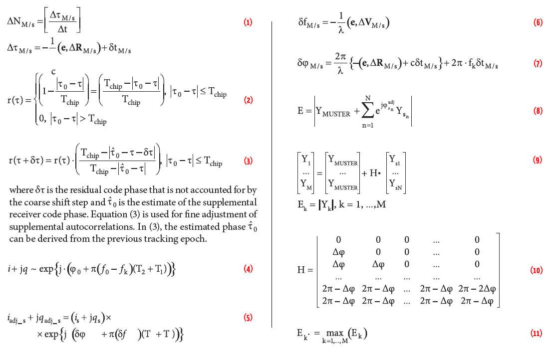
The adjustment procedure first computes the integer number of samples that corresponds to the relative MUSTER/supplemental code phase and then shifts the supplemental autocorrelation accordingly. The integer number of samples is determined as follows:
Equation 1 (see insest photo, above right, for all equations in this article)
where:
[] is the whole part;
Δt is the autocorrelation sampling interval;
ΔRM/s is the estimate of the relative MUSTER/supplemental position vector;
e is the satellite-receiver line-of-sight (LOS) vector that can be computed based on satellite ephemeris (or almanac) and approximate knowledge of the receiver position. Note that for cases where spatial separation of networked receivers stays within 100 meters, a position estimate applied to compute the LOS unit vector need only be known within 200 kilometers to support a one-meter accurate computation of relative code phase;
(,) is the vector dot product;
c is the speed of light; and,
δτM/s is the estimate of the relative MUSTER/supplemental clock state.
The coarse shift allows adjustment of autocorrelation functions, but only within the resolution of their sampling interval.
Remaining autocorrelation offsets can still degrade the code-tracking performance. To illustrate, for the 0.2-microsecond sampling interval (i.e., when the GPS signal is sampled at five mega-samples-per-second), the remaining offset is 0.1 microsecond (or 30 meters, equivalently) in the worst-case scenario.
Combining two autocorrelation functions with a 30-meter offset can significantly degrade the code-tracking performance.
Therefore, a fine adjustment step is implemented. To derive fine adjustment, a normalized code autocorrelation, r(t), is first expressed as:
Equation 2
where Tchip is the code chip duration and τ0 is the true offset of the received code. Next, Equation (3) is applied to relate the values of the autocorrelation function at τ and τ+δt:
Equation 3
Alternatively, an iterative procedure can be applied. In this case, the MUSTER code phase is first estimated using the coarse shift only. This estimate, along with estimates of relative position and clock states, is then used to compute the estimate of the supplemental code phase in Equation (3). Finally, the fine shift is implemented and the code phase estimation is refined. Note that the autocorrelation adjustment procedure is applied for every Doppler frequency shift from the frequency search space.
We perform carrier adjustment by adjusting phases of one millisecond accumulated is and qs. Particularly, it can be shown that one millisecond–accumulated complex signal amplitude is expressed as follows:
Equation 4
where:
φ0 and f0 are the initial phase and carrier frequency of the incoming signal;
fk is the frequency that corresponds to the kth Doppler shift from a one-millisecond Doppler search space; T1 and T2 are the beginning and end time of a one-millisecond interval, respectively.
Correspondingly, one-millisecond is and qs of supplemental receivers are adjusted as follows:
Equation 5
where δφM/s is the difference in initial phase between MUSTER and supplemental receiver, and, δfM/s is the difference in MUSTER/ supplemental Doppler shifts computed as:
Equation 6
In (6), ΔVM/s is the relative velocity vector and λ is the carrier wavelength. Equation (7) formulates the phase difference:
Equation 7
The third term in Equation (7) compensates for the satellite/ platform LOS motion that occurs between asynchronous sampling of one-millisecond functions at MUSTER and supplemental receivers. When clock synchronization offsets between different platforms exceed 10 milliseconds, the contribution of the third term can exceed a centimeter level, which is critical for maintaining the carrier coherency. Hence, the third term is used to ensure robust operations for a general non-synchronous clock scenario.
Also note that, if networked receivers stay within 100 meters of each other, then for LOS unit vector computations the MUSTER receiver location must be known within one kilometer in order to maintain carrier phase and enable coherent combination of signals from multiple platforms. If such information is not available, then we can still apply a non-coherent combination.
Following the adjustment of supplemental one-millisecond functions, MUSTER accumulates them (as well as its own one-millisecond function) beyond the one-millisecond interval. A combined coherent/non-coherent accumulation approach is used. A 20-millisecond coherent accumulation is implemented first, which is followed by the optional non-coherent accumulation over an extended interval such as 0.1 second or one second.
The advantage of using non-coherent accumulation is the addition of high-sensitivity receiver capabilities to MUSTER (without the need to add inertial sensors for accumulation aiding).
The apparent drawback is the loss of carrier phase tracking. Note, however, that most prospective applications of MUSTER aim at positioning accuracies on the order of a few meters; so, precise positioning capabilities are not required, and disabling carrier phase tracking does not represent a critical issue.
We now add multi-platform accumulation results together (coherently or non-coherently). The result is the combined multi-platform signal image, which is directly applied for the estimation of signal parameters (code and carrier) using the open-loop tracking approach.
Multi-Platform Signal Tracking for Uncertain Relative States
The previously discussed methods of multi-platform signal accumulation assume that relative navigation states of networked receivers are precisely known. If relative navigation states are only approximately known, we need to modify signal-processing methods.
In exploring such cases, we make the following assumptions:
1) relative position between networked receivers is known only within 100 meters
2) relative receivers’ velocity is known within two meters per second
3) relative clock states are calibrated with an accuracy of 100 nanoseconds or, equivalently, 30 meters accuracy.
Note that we do not assume relative clock synchronization at this level of accuracy. Our assumption means that estimates of relative clock biases are accurate within 100 nanoseconds, while biases themselves can stay at a much higher level (for example, at a sub-millisecond level), and different receiver platforms essentially operate in the asynchronous mode.
The foregoing assumptions for relative position and velocity accuracies are supported for the majority of MUSTER applications such as pedestrians (for example, a group of cell phone users), a swarm of unmanned aerial vehicles (UAVs), or a team of unmanned ground vehicles (UGVs). For such cases, users normally stay within 100 meters of each other and their velocity values do not differ by more than two meters per second. Hence, zero relative position and velocity can be simply assumed.
We can maintain the 100-nanosecond relative clock accuracy by using a communication data link in order to estimate relative clock biases (via two-way ranging). In this case, the “ballpark” calibration accuracy is 10 percent of the data rate. For example, for a one-megahertz link, this results in 100-nanosecond accurate estimates of relative clock delays.
Alternatively, receivers can incorporate inexpensive but relatively stable clock oscillators (such as oven-controlled crystal oscillators or OCXOs) that are pre-calibrated at the beginning of the mission (in benign signal environments) and then maintain the required relative clock accuracy in difficult environments over long periods of time (a few hours).
For practical purposes, let’s assume the following scenario: Reasonably spaced networked receivers have unknown relative positions and velocities and lack any external aids. Relative clock biases are estimated using the communication data link or based on pre-calibrated receiver clocks.
For this scenario, a modified MUSTER architecture can efficiently combine weak GPS signals (coherently or non-coherently), mitigate the influence of relative state uncertainty on the tracking accuracy, and enable the overall position estimation that is accurate at a level of a few meters (as test results will show later).
We enable carrier phase tracking by adjusting phases of supplemental receivers in order to maximize the combined multi-platform signal energy. Possible phase adjustments are searched through and the maximum-energy adjustment combination is chosen. This is implemented as follows. For a specific set of phase adjustments, the multi-platform signal energy is computed as:
Equation 8
where:
YMUSTER is the 20-millisecond accumulated complex amplitude of the MUSTER receiver that corresponds to code phase and carrier frequency of the maximum-energy point in the multi-platform signal image constructed using non-coherent accumulation: i.e., 20-millisecond MUSTER and supplemental signal images that are added non-coherently, and selected code and frequency values that correspond to the maximum energy point;
Ysn is the 20-millisecond accumulated complex amplitude of the snth supplemental receiver (again using complex amplitude for code phase and carrier frequency of the maximum energy point of the non-coherent multi-platform signal image); is the phase adjustment applied to the snth supplemental receiver; N is the total number of supplemental receivers; and, | | is the absolute value.
The maximum energy value is searched extensively through all possible combinations of phase adjustments. Due to the cyclic nature of the carrier phase, the adjustments only need to be searched in the range from 0 to 2π. The search is implemented based on matrix multiplication:
Equation 9
where M is the number of phase combinations to search through and matrix H contains all possible combinations of phase adjustments, i.e.:
Equation 10
In Equation (10), Δφ is the resolution of the phase adjustment search. We determined empirically that the phase search resolution of π/2 is sufficient for consistent carrier phase tracking.
After computing the signal energy for all possible phase adjustments, the maximum energy is defined as
Equation 11
Its associated signal amplitude, Yk*, is then applied to track the carrier phase (using the open-loop tracking method).
The apparent drawback of the phase-adjustment approach is that its complexity grows exponentially with the increased number of networked receivers. The carrier phase can still be tracked for relatively small receiver networks, for example those including three or five nodes.
For a large number of cooperative receivers, however, the computational burden will prevent the phase tracking capability: i.e., centimeter-accurate ranging ability will be lost. However, in this case, signals from multiple platforms can still be combined non-coherently. As a result, code and carrier frequency can still be tracked efficiently even without compensating for the relative phase difference between networked receivers.
For code tracking, the assumed uncertainties in networked receivers’ navigation states do not lead to severe energy losses and still enable accumulation of weak GPS signals from multiple platforms. For instance, a maximum energy loss due to a 100-meter position offset is about 3 decibels. Therefore, we do not need to compensate for relative state offsets to maintain efficient accumulation of multi-platform signal energy and support the code and frequency tracking status.
Unknown relative states, however, can significantly degrade code-tracking quality. For example, the addition of two autocorrelation functions with a 100-meter offset between them distorts the autocorrelation shape and introduces significant ranging errors.
To illustrate the influence of relative state errors, a simulation scenario was implemented for a three-platform network as shown in Figure 5.
In Figure 5, eSV is the unit vector pointed toward the satellite. Projections of relative MUSTER/supplemental positions on the satellite LOS are 39.2 meters and 33.0 meters for supplemental receivers 1 and 2, respectively.
Stationary receivers were simulated. C/A code tracking was implemented with a 20-millisecond signal accumulation interval. The carrier-to-noise ratio (C/N0) was 28 dB-Hz. The signal processing part assumed zero relative position states. Relative clock calibration errors for both supplemental receivers were set at 20 meters.
Figure 6 shows the results of this simulation: MUSTER signal processing still enables consistent code tracking for a 28 dB-Hz GPS signal, which a single unaided GPS receiver cannot track. However, uncompensated uncertainties in relative position states introduce a ranging bias of -39.5 meters.
This simulation example clearly demonstrates that the signal tracking quality is significantly degraded if relative navigation errors are not accounted for. Hence, we developed an algorithm to compensate for uncertainties in relative receivers’ states and enable unbiased tracking of the code phase.
This algorithm first estimates unknown relative ranges that are a combined effect of a) projections of relative position uncertainties on the satellite/receiver LOS and b) clock calibration errors. Relative range estimates are then applied to shift supplemental autocorrelation functions before they are added to the MUSTER GPS signal image.
Figure 7 illustrates the algorithm that estimates unknown multi-platform ranges. The algorithm finds a shift that needs to be applied to each supplemental autocorrelation in order to maximize the energy in the combined MUSTER/ supplemental signal image.
For each range adjustment from the relative range search space, supplemental autocorrelation is shifted correspondingly and then added (non-coherently) to the MUSTER autocorrelation. An energy peak of this combined autocorrelation is defined and stored by the MUSTER software module. As a result, the MUSTER/supplemental signal energy is constructed as a function of the relative range.
The maximum of this function corresponds to the correct value of relative range. Theoretically, this function has a triangular shape, wherein the base of the triangle is equal to the double duration of the code chip converted into the units of meters. So, the relative range is estimated by fitting a triangle through the energy function constructed by shifting the supplemental autocorrelation though the relative range search space.
Note that the search space herein is defined by the position uncertainty (100 meters, maximum value) and clock calibration errors (30 meters, one sigma value). Currently a ± 200 meter search is applied with the search resolution grid being equal to 20 meters.
*One further note: the relative range is estimated independently for each supplemental receiver.
In principle, a combined search could be used similar to the carrier phase adjustment search described earlier. However, such an approach requires the use of a multi-dimensional curve fit, which was found to be unreliable, especially for large receiver networks. Moreover, the computational load of the combined search grows exponentially with the increased number of receiver nodes.
Therefore, our approach estimates the relative range for each individual supplemental receiver. In this case, the curve fitting is one-dimensional and works reliably; the computational complexity grows only linearly when additional receivers are included.
The relative range estimation approach is based on using signals from only two receivers. This obviously increases relative range estimation noise as GPS signals weaken and, consequently, increases the level of noise in code phase measurements. However, code phase measurements are unbiased.
To illustrate this latter point, Figure 8 exemplifies simulation results for the three-platform simulation scenario shown earlier in Figure 5. The noise level increases considerably as compared to the case where relative range differences are not compensated for (see Figure 6): 46.4 meters standard deviation versus 23.2 meters standard deviation, respectively.
However, estimation of relative ranges removes the measurement bias: -0.3 meter versus -39.5 meters mean error for compensated and uncompensated cases, respectively.
The examples of simulation results shown in Figures 6 and 8 clearly demonstrate the complementary nature of code phase tracking with and without relative range compensation: biased, lower noise versus unbiased, higher noise. Noisy but unbiased measurements can be combined with (relatively) low-noise but biased measurements that occur when relative position errors are not compensated for. The result is a low-noise, unbiased measurement of the code phase.
It is also worth mentioning that, as the C/N0 level drops, relative range estimates for some receivers can become unreliable, that is, they can have measurement outliers. Such outliers are detected by identifying the estimates that are outside of the relative range search space. Supplemental functions with unreliable relative range estimates are then simply excluded from the overall signal accumulation process.
For low C/N0 levels, the increased number of outliers (and increased number of associated supplemental functions excluded from signal accumulation from time to time) is balanced by the fact that more receivers are added to the network and a temporary exclusion of one or even several of them does not significantly compromise the overall accumulated signal power.
Figure 9 illustrates the overall tracking approach. A difference between biased and unbiased measurements is computed and then smoothed by a Kalman filter. The method also monitors unbiased measurements for possible noise spikes by detecting outliers in the filter innovation sequence. The Kalman filter outputs the estimated bias value, which is then subtracted from biased measurements to produce the final measurement of the code phase.
Note that when the relative position and clock states are constant (i.e., for stationary receivers and zero relative clock drifts) the bias in code phase measurements is quasi-stationary and changes very slowly with changing satellite geometry.
For a general case of non-stationary receivers and non-zero relative clock drifts, the bias is kept quasi-stationary by propagating relative ranges based on Doppler measurements from MUSTER and supplemental receivers. Note also that when Doppler estimates are applied to propagate the relative range, the system noise matrix of the Kalman filter (generally referred to as the Q-matrix) is defined by the covariance of the noise in the Doppler measurements.
Figure 10 shows example results for the combined (bias/unbiased) code-tracking scheme. For completeness, we modified the three-platform simulation scenario described previously into a non-stationary case. The network configuration started as shown in Figure 5. Receivers then moved with non-zero velocities respectively set as [2; 1; 0], [3; 2; 0], and [4; 2; 0] meters per second for the MUSTER and two supplemental receivers.
The scenario implemented the MUSTER tracking functionality on all three platforms and used Doppler estimates obtained by all three receivers to propagate the relative range estimate from its initial state.
Simulation results presented show that the combined tracking approach enables unbiased measurements of the code phase while maintaining a level of noise that is identical to the performance of biased estimation (23.4 meters versus 23.2 meters for two example cases).
The approach developed to estimate relative Doppler frequencies is similar to the estimation of the code phase.
Figure 11 summarizes the MUSTER tracking architecture developed to incorporate cases of uncertain relative states. Relative navigation states are initialized based on clock calibration results only: zero relative position and velocity are assumed. These initial states are then propagated over time based on MUSTER/supplemental tracking results (Doppler frequency estimates and higher- order Doppler terms).
We compute code and frequency tracking states by combining biased and unbiased measurements. Biased measurements are obtained by adjusting supplemental signal images for approximately known relative states only. Unbiased measurements are determined by using relative range/Doppler correction algorithms that estimate range and frequency adjustments for each supplemental receiver.
The Kalman filter that supports the optimal combination of biased and unbiased tracking measurements also includes code-carrier smoothing to mitigate noise in measured code phase. For those cases that coherently combine multi-platform signals, MUSTER uses a standard carrier phase smoothing approach When non-coherent signal combinations are involved, a “pseudo”–carrier phase is first derived by integrating Doppler estimates over time and then applied to smooth the code phase.
Experimental Results
In this section, we will demonstrate the performance of multiplatform signal tracking using experimental data. Figure 12 shows a photograph of the test setup that was developed for the collection of test data from three independent (i.e., non-collocated and non-synchronized) receiver platforms.
As shown in the upper image in Figure 12, the setup established three receiver nodes at roof, rack, and cart locations. The roof and rack nodes remained stationary for all test scenarios, while the cart has the ability to move in order to test dynamic cases.
Each node in the data collection setup includes a pinwheel GPS antenna, a radio-frequency (RF) front-end, an external clock for the front-end stabilization, and a data collection computer. The lower image in Figure 12 shows this equipment in the cart node.
Figure 13 portrays the data collection environment for our tests. We performed two scenarios that included static and dynamic (L-shape motion trajectory) tests. As shown in the figure, the tests established a significant separation (on the order of 100 meters) between individual nodes.
GPS signal sampling for individual nodes was performed completely independently from each other, thus implementing a truly asynchronous receiver network in order to test the most generic case of MUSTER functionality.
For data collection, we focused on selection and implementation of a low-cost front-end option, using a networkable software radio board containing an FPGA, dual analog/digital and digital/analog converters, and gigabit Ethernet connectivity.
Analysis of signal tracking results for individual nodes indicated that the board’s native clock was not stable enough for MUSTER purposes. (It exhibited clock drift variations on the order of five meters per second, which prevents reliable multi-platform signal accumulation.)
Consequently, we augmented data collection with a clock-stabilization option, initially using atomic clocks. However, lower-cost OCXOs would also be sufficient to enable reliable clock stabilization for multi-platform tracking purposes.
Prior to multi-node signal processing, receiver clock states of individual nodes were initialized using a single-node tracking of open sky GPS signals. These clock estimates were then applied to initialize relative clock state for MUSTER tracking.
The test system collected raw GPS signal samples for all three nodes and stored them in the laptop computer for post-processing. We considered two options for GPS signal attenuation: software injection of broadband noise and natural signal attenuation by surrounding trees and buildings at the test location.
Figure 14 illustrates the approach applied for the evaluation of MUSTER tracking performance using the first option. Here, software-generated broadband noise was injected into raw GPS signal samples to demonstrate performance in a controlled signal attenuation environment.
In this option, after using software to inject noise into open-sky GPS satellite transmissions, the multi-platform tracking architecture processed the attenuated signals. We also conducted single-node tracking of open-sky signals in order to generate reference tracking measurements (code and carrier phase).
Multi-platform tracking errors were computed as differences between MUSTER tracking results and reference tracking data. Figures 15 and 16 provide results for static and dynamic test cases, respectively, in which coherent signal integration was applied.
For both test cases the GPS signal was attenuated to a level below the tracking threshold of a single node GPS receiver (which corresponds to the C/value of 32 dB-Hz). Multi-platform tracking was performed with a 28 dB-Hz signal for the static case and 29 dB-Hz for the dynamic case. The results demonstrated reliable multi-node code and carrier phase tracking of attenuated GPS signals.
The results further show carrier phase accuracy at the sub-centimeter level. Specifically, carrier phase errors are estimated as -0.3 millimeter (mean) and 8.4 millimeters (sigma) for the static case and -0.1 millimeter (mean) and 8.1 millimeters (sigma), for the dynamic case. Errors in carrier-smoothed code measurements generally stay at a level of a few meters with steady-state errors not exceeding six meters.
Figures 17 through 20 show example test results for the case where we applied a combined coherent/non-coherent signal accumulation scheme. In these examples, single node signals are first accumulated coherently over 20 milliseconds, followed by non-coherent accumulation over 0.1 second. Single node– accumulation results are then non-coherently added to enable MUSTER signal tracking.
The use of extended non-coherent accumulation enables tracking of much weaker GPS signals (as compared to the 20-millisecond coherent accumulation). This combines MUSTER and high-sensitivity receiver capabilities but leads to the loss of the carrier phase tracking status. However, as mentioned previously, for many applications of MUSTER (such as indoor LBS), precise positioning is not required and loss of the carrier phase is not critical.
For the test examples presented here, GPS signals were attenuated to the level of 15-18 dB-Hz, which is generally experienced in very difficult environments, such as urban canyons and indoors. (See the articles by A. Soloviev et alia and G. Lachapelle et alia in Additional Resources for more details on these difficult environments).
All test scenario results (including static and dynamic cases) demonstrate reliable multi-platform code tracking. Note that the carrier-smoothed code for cases of very weak GPS signals generally required a longer convergence period (60 seconds or longer). Once the convergence was achieved, code phase errors stayed at a level of a few meters.
Figure 21 shows test results for the second signal-attenuation option where natural signal propagation obstacles were present. In this case, a complete position solution was derived from the five highest-elevation satellites for a loop test trajectory. We chose a trajectory in which selected portions were close to trees, buildings, and a metal container — thus creating a GPS-degraded test.
Figure 21 compares trajectory reconstruction results (shown in Google Earth) for cases of single-node and multi-node signal processing. For both cases, we implemented a 20-millisecond signal accumulation and estimated the position solution from carrier-smoothed code measurements.
As shown in Figure 21, discontinuities are present in the single-node solution, while MUSTER signal tracking maintains consistent position estimates. Using Google Earth tools, we determined that worst-case single-node position errors are in the range of 10–20 meters, while multi-node signal processing supports meter-level positioning accuracy.
The test results validate the MUSTER tracking functionality with experimental data and show the efficacy of the approach for the processing of weak GPS signals.
Conclusions
This article described the concept of a networked GNSS receiver and applied it to the processing of weak GPS signals.
The discussion introduced algorithmic approaches of multi-platform signal tracking and a methodology that specifically addresses cases where relative navigation states (i.e., position, velocity, and clock) between individual receiver nodes contain large uncertainties (e.g., 100-meter position uncertainty).
Test results demonstrate multi-platform tracking (including code and carrier phase) of weak signals for individual satellite channels applying software-based signal attenuation.
Future work will further evaluate multi-node signal tracking for challenging GPS signal scenarios such as indoors. The MUSTER tracking functionality (currently being evaluated in post-processing) will also be implemented and demonstrated in a real-time operational mode.
Acknowledgment
This work was funded, in part, by the Air Force Small Business Innovation Research (SBIR) grant, Phase 1 and Phase 2, topic number AF103-185, Program Manager Dr. Eric Vinande. The article is based on a presentation made at the Institute of Navigation International Technical Meeting in San Diego, California, USA.
Additional Resources
[1] Lachapelle, G., and H. Kuusniemi, D. T. H. Dao, G. MacGougan, and M. E. Cannon, “HSGPS Signal Analysis and Performance Under Various Indoor Conditions,” NAVIGATION, Vol. 51, No. 1, Spring 2004, pp. 29–44
[2] Soloviev, A., and D. Bruckner, F. van Graas, and L. Marti, “Assessment of GPS Signal Quality in Urban Environments Using Deeply Integrated GPS/IMU,” Proceedings of The Institute of Navigation National Technical Meeting, January 22–24, 2007, San Diego, California
[3] Soloviev, A., and J. Dickman, “Extending GPS Carrier Phase Availability Indoors with a Deeply Integrated Receiver Architecture,” IEEE Wireless Communications, Vol. 18, No. 2, 2011
[4] van Graas, F., and A. Soloviev, M Uijt de Haag, and S. Gunawardena, “Closed Loop Sequential Signal Processing and Open Loop Batch Processing Approaches for GNSS Receiver Design,” IEEE Journal of Selected Topics in Signal Processing, Vol. 3, Issue 4, August 2009
