
A novel approach for GPS M-code pull-in. Signal acquisition and tracking are two essential functions of a satellite navigation (satnav) receiver that allow it to form a position, velocity and time (PVT) solution.
RYAN S. CASSEL, LAWRENCE ELENTUKH, SHAWN D. MILLER, THE MITRE CORPORATION
Acquisition is the process in which the receiver searches for a satellite signal and obtains a coarse estimate of its delay and frequency. Tracking is the process in which the receiver maintains accurate estimates of the delay, frequency and phase of the signal to measure the pseudorange and demodulate navigation data. In between acquisition and tracking is a process called handover, where the coarse delay and frequency estimates from acquisition are “handed over” to a tracking loop to begin tracking the signal.
The accuracy of the handover estimates depends on many factors, including signal dynamics and carrier-to-noise ratio. For example, detecting a signal at low carrier-to-noise can require long dwell times, during which time the signal can migrate in time and frequency due to dynamics. Depending on the accuracy of the delay and frequency estimates used to initialize the tracking loops, they may need to pull in over large initial delay and frequency errors.
For binary offset carrier (BOC) signals that have auto-correlation functions (ACFs) with multiple peaks, like GPS M-code, unambiguous code discriminators using extra correlation taps can remove the effects of the correlation ambiguity and extend the code pull-in range. Unambiguous discriminators for BOC signal tracking have been widely developed and documented in the literature, including for GPS M-code and [5] for GPS L1C and Galileo E1 OS. However, during code pull-in, the prompt tap, which is typically used for carrier tracking, traverses the peaks and nulls of the ACF, alternating between high and low correlation power. When the prompt tap lands in a null, carrier tracking accuracy suffers and pull-in can fail.
To mitigate the effects of this phenomenon and increase code pull-in range, we developed a novel technique called dynamic carrier tap selection (DyCaTS) for pull-in on GPS M-code with an unambiguous eight-gate discriminator derived in [3] and presented in [4]. The tap used for carrier tracking is dynamically selected during code pull-in based on which has the highest correlation output power accumulated over a moving window of configurable duration. The configurable window allows the technique to be tuned for different signal dynamics, carrier-to-noise ratios, and expected pull-in speeds. Because DyCaTS selects from the taps that are already used for code tracking and does not require additional taps, it has low implementation cost and can be applied to any tracking loops for any GNSS signals.
We show through Monte Carlo simulation that at low carrier-to-noise, DyCaTS can increase the M-code one-sided pull-in range using an unambiguous eight-gate discriminator by five times, from just 0.1 chips to more than 0.5 chips, thereby significantly increasing the code tracking loop’s robustness against initial delay errors handed over from acquisition. Similarly, if a signal has migrated considerably in delay during acquisition, DyCaTS can reduce the number of different code tracking loops, each initialized at a different delay, needed to “re-find” the signal, because each loop now effectively covers a larger range of delays.
Code Pull-In
The handover process involves initializing the code and carrier tracking loops with the delay and frequency estimates from acquisition. Because the carrier phase is generally unknown directly following acquisition, carrier pull-in is often performed with a frequency-locked loop (FLL) instead of a phase-locked loop (PLL). The FLL permits arbitrary phase errors, unlike the PLL, and is widely known to be more tolerant of frequency errors and dynamics than the PLL, making it the natural choice for pull-in.
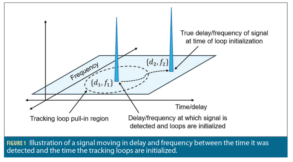
Under benign conditions with high carrier-to-noise ratios and low signal dynamics, the handover process can be quite trivial. The delay and frequency estimates handed over to the tracking loops are accurate, and the tracking loops can pull in over small initial errors and quickly reach steady-state tracking. However, under challenging conditions, handover can be more difficult. Long acquisitions (due to low carrier-to-noise) and high dynamics (specifically, rapidly changing Doppler) can result in the signal migrating in delay and frequency between the time it was initially detected and the time the tracking loops are initialized.
This is depicted in Figure 1. If a tracking loop is initialized with delay d1 and frequency f1 but the signal has migrated to delay d2 and frequency f2 outside the pull-in region, then the tracking loops will not be able to successfully track the signal. The problem of signal migration is even more prevalent in “store-and-process” acquisition architectures where a snapshot of the signal is recorded and processed for acquisition (as opposed to “real-time” or “streaming” architectures), further increasing the error between true signal delay and frequency and estimated delay and frequency used for tracking loop initialization.
The key to maximizing the probability of successful pull-in or minimizing the number of separate tracking loops, each initialized at a different delay and frequency, needed to “re-find” the signal after it has migrated (and therefore minimizing the required hardware and software resources) is to maximize the pull-in region of each tracking loop. The pull-in ranges are determined by the carrier-to-noise ratio and the discriminator S-curves, which describe the relationship between the discriminator inputs (the correlation outputs) and the discriminator output (a measurement of the parameter of interest, such as frequency error or code delay). Because DyCaTS primarily impacts code pull-in, we will focus on the code tracking loop.
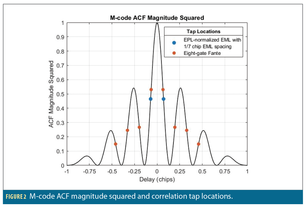
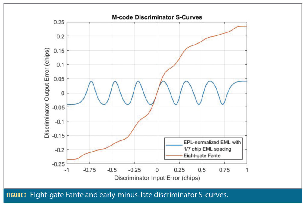
Figure 2 shows the magnitude squared of the M-code ACF bandlimited to 30.69 MHz. Because it has multiple peaks, a simple early-minus-late code discriminator will not produce a wide pull-in range and will be susceptible to tracking the side peaks. We therefore consider the “eight-gate monotonic Fante M-code discriminator,” derived in [3], named after its designer, and presented in [4], which is specifically designed for unambiguous full-band M-code tracking with a wide pull-in range. Figure 3 shows the discriminator S-curves of the Fante discriminator and an early-minus-late power discriminator (normalized by early-plus-late power) with an early-minus-late tap spacing of 1/7 chips. Both S-curves assume a precorrelation bandwidth of 30.69 MHz and a carrier-to-noise ratio of C/N0∞ and use the discriminator gains from [4]. The tap locations for the two discriminators are also shown as dots overlayed on the ACF magnitude squared in Figure 2.
The most important feature of the Fante discriminator is its S-curve only has one zero-crossing (and is therefore unambiguous) and a much wider pull-in range than the early-minus-late discriminator, possibly up to ±1 chip. However, the pull-in range of the Fante discriminator cannot be predicted analytically at low carrier-to-noise because the S-curve is not linear, and therefore the loop does not behave like a linear system. As a result, we can use the shape of the S-curve to inform an expected pull-in range, but it must be verified in simulation.
There is another reason pull-in ranges cannot be predicted analytically at low carrier-to-noise: The code and carrier tracking loops are coupled together. When carrier-to-noise is high and each loop is tracking accurately, the coupling can be ignored. This allows the two loops to be treated independently, a common approach for predicting loop performance. However, when carrier-to-noise is low and tracking errors are not small, the performance of each loop can have a considerable impact on the other. If carrier frequency tracking errors are large, then correlation power is lost in all taps, and code tracking accuracy will suffer. If code tracking errors are large, then the prompt tap will not lie at the peak of the correlation function, and carrier tracking will suffer. This second phenomenon is the one we will specifically address with DyCaTS.
DyCaTS
While the eight-gate Fante discriminator S-curve in Figure 3 suggests a pull-in range up to ±1 chip, consider that for large initial delay errors, the correlation power at the prompt tap (which is usually used for carrier tracking) may be significantly reduced. For example, if the initial code delay error is larger than 0.5 chips, then from Figure 2, the correlation power loss at the prompt tap will be at least 6 dB. At low carrier-to-noise, an additional 6 dB loss may result in loss-of-lock and failure to pull in. Furthermore, during code pull-in, the prompt tap must traverse the peaks and nulls of the squared ACF. Even if an initial 6 dB of loss due to a delay error of 0.5 chips can be tolerated, the prompt tap will still have to traverse the first two nulls. When the prompt tap happens to land in a null, there will be no correlation power available for carrier tracking.
Mitigating this issue starts by recognizing not all nine taps (eight for the Fante discriminator, plus prompt) can simultaneously lie in nulls in the squared ACF. At least one tap has correlation power that can be used for carrier tracking, even if it is not the prompt tap. Because all taps are at the same phase, we can in principle select any tap to use for carrier tracking. To identify which of the nine taps should be used, we accumulate the magnitudes squared of the correlation outputs at each tap over a configurable moving window. The tap with the highest accumulation over the window has the maximal post-correlation SNR. Therefore, its in-phase and quadrature components are input to the frequency discriminator for carrier tracking.
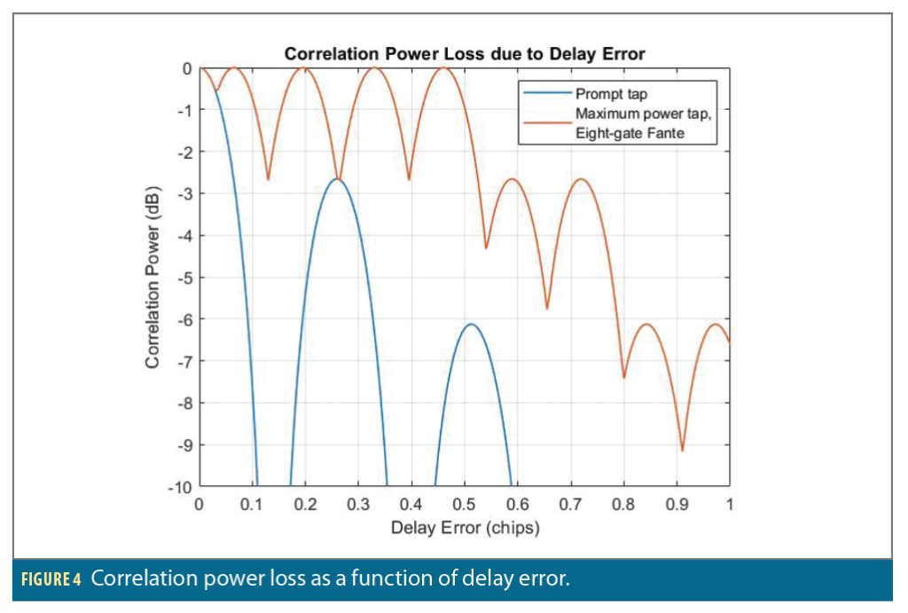
Figure 4 shows the correlation power loss as seen by the carrier tracking loop as a function of delay error with and without DyCaTS. The blue curve indicates the correlation power loss of the prompt tap (i.e., without DyCaTS) as a function of delay error, and the red curve indicates the correlation power loss of the maximum-power tap (i.e., with DyCaTS), including the prompt, using the Fante discriminator. As the prompt tap approaches a null, correlation loss approaches ∞ dB. However, selecting the maximum-power tap for carrier tracking reduces the correlation power loss due to delay error. For example, if the initial delay error is 0.5 chips, then selecting the maximum-power tap incurs a maximum loss of just 2.7 dB over the pull-in process.
Monte Carlo Simulation Setup
Because pull-in ranges at low carrier-to-noise cannot be predicted analytically, we will use Monte Carlo simulation. The general procedure will be to parameterize the initial delay (and frequency) errors of the tracking loops and quantify the probability of successful pull-in over many Monte Carlo trials.
We leverage the simulation capability of MITRE’s Global Navigation Satellite System Test Architecture (GNSSTA) [6], which, instead of processing radio frequency signals or baseband data, emulates the sample-rate processing by generating synthetic correlation outputs using a well-known model. It therefore facilitates faster-than-real time Monte Carlo simulation. The vector of real-valued in-phase (I) and quadrature (Q) correlation outputs is

where n is the number of correlation taps (including prompt). It is distributed according to x~N(μ,Σ). The expected value μ is given by [7]
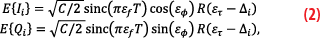
where C is the signal power in the component being processed (in our case, the M-code pilot), T is the coherent integration time, R(∙) is the bandlimited ACF at the argument, Δi is the delay of correlation tap i relative to prompt, and εf, εϕ, and ετ are the frequency, phase and delay errors between the signal and the replica, respectively. The covariance matrix Σ is given by [7]
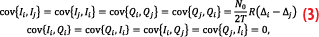
where N0 is the white noise power spectral density and R(0)=1. The well-known limitation to this model is it assumes εf is constant over the coherent integration interval and that εϕ represents the average phase error over the interval, which is not the case when Doppler changes over the interval. To mitigate this effect, we limit our simulations to low line-of-sight acceleration and zero jerk.
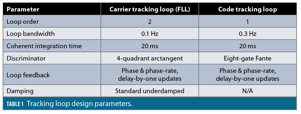
We employ a typical carrier-aided code tracking architecture shown in Figure 5. The carrier tracking loop is an FLL described in [8] and the code tracking loop is based on the design in [9]. Table 1 lists the tracking loop design parameters. The second order FLL tracks line-of-sight acceleration with zero steady-state frequency error, and the code loop can be made first order because it is carrier-aided. The loop bandwidths are small to filter out noise at the low carrier-to-noise ratios we are concerned about. Also, the code discriminator outputs are normalized by the gains derived in [4].
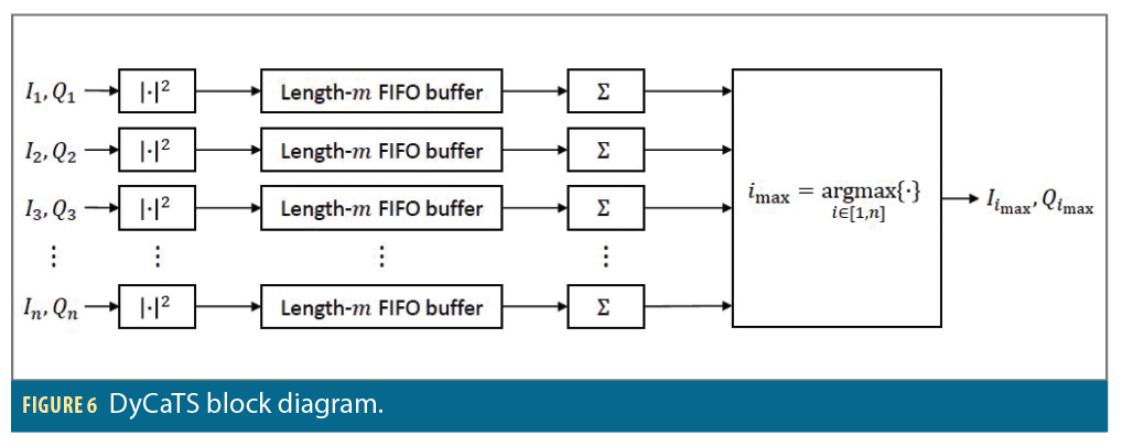
The DyCaTS block in Figure 5 is further detailed in Figure 6. The I and Q correlation outputs from all n=9 taps are passed into the DyCaTS block. The I and Q values for each tap are then magnitude-squared and sent into a first-in, first-out (FIFO) buffer of configurable length m coherent integration intervals. Then the elements of the buffer are summed together. The sums from all n buffers are compared, and the index of the maximum is designated imax. DyCaTS then passes the I and Q correlation outputs from the current coherent integration interval corresponding to tap imax into the frequency discriminator.
DyCaTS can be used on any number of taps n. For example, it could be used on the five correlation outputs for unambiguous BOC(1,1) tracking described in [5], or even on just three correlation outputs for typical early-minus-late tracking of BPSK-R signals. The FIFO buffer length m also can be configured and has the same inherent tradeoffs of any digital signal processing algorithm: Larger values of m make the DyCaTS output track the actual maximum-power tap smoothly but slowly, while smaller values of m make the DyCaTS output track the actual maximum-power tap rapidly but noisily. In the case of m=1, DyCaTS simply passes the I and Q correlation outputs from the tap with highest instantaneous power.
We simulate at C/N0=20 dB–Hz on the M-code pilot component, which represents a low carrier-to-noise at which long acquisitions may be necessary and signal migration in delay and frequency could yield large initial delay and frequency errors in the tracking loops. We also simulate a line-of-sight acceleration between transmitter and receiver of 3 m/s2, which is nonzero but low enough that the correlation model is still accurate.

To quantify the tracking loop pull-in ranges, we manually introduce delay and frequency errors, δd and δf, respectively, at tracking loop initialization. If the true delay and frequency of the signal are d and f, respectively, then the initial delay and frequency of the tracking loops are
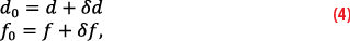
We determine whether pull-in was successful by comparing the estimated signal Doppler to the true Doppler. If Doppler errors are large enough, loss-of-lock occurs and pull-in fails. We compute a smoothed Doppler estimate from the tracking loop by averaging Doppler estimates from three successive coherent integration intervals and declare successful pull-in if the relative error between the smoothed Doppler estimate and the true Doppler is less than 10% at least 90% of the time over the course of a 200 second simulation. We confirmed the accuracy of this criteria by visually comparing the true Doppler to the estimated Doppler and ensuring divergence was detected accurately.
Monte Carlo Simulation Results
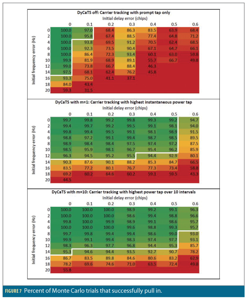
Figure 7 shows the percentage of Monte Carlo trials that pull in successfully as a function of the initial delay and frequency errors. The rows correspond to different initial frequency errors δf in hertz and the columns correspond to different initial delay errors δd in chips. Each cell shows the percentage of 1,000 independent Monte Carlo trials that successfully pulled in. We also show the approximate 95% success contour with a white line. The top table has DyCaTS turned off, meaning the prompt tap is always used for carrier tracking. The middle table uses DyCaTS with m=1 coherent integration interval, meaning the tap used for carrier tracking is the one with the highest instantaneous correlation output magnitude squared. The bottom table uses DyCaTS with m=10 coherent integration intervals.
Notice there is a correspondence between the columns in the top table of Figure 7 that have the lowest success percentages and the correlation power losses due to delay error when using the prompt tap in Figure 4 (the blue curve). For example, an initial delay error of ±0.3 chips results in an initial correlation power loss of 3.8 dB, while initial delay errors of ±0.2 or ±0.4 chips result in initial losses of 5.4 and 29.3 dB, respectively. Thus, pull-in with an initial delay error of ±0.3 chips is successful more often than with an initial delay error of ±0.2 or ±0.4 chips.
The middle table in Figure 7 shows even using DyCaTS with m=1 can significantly increase the delay pull-in range. With DyCaTS off, the 95% pull-in range is no more than 0.1 chips, whereas DyCaTS with m=1 extends the pull-in range to about 0.5 chips. Returning to Figure 4, using the maximum power tap of the eight-gate Fante discriminator (the red curve) for carrier tracking yields much higher post-correlation SNR on average than simply using the prompt tap (the blue curve).
The bottom table in Figure 7 shows increasing the tap selection window from m=1 to m=10 can produce marginally better performance. Summing the tap magnitudes squared for 10 intervals instead of just one reduces the susceptibility to selecting a tap due to powerful noise on that tap at a single interval. In other words, it results in a smoother and more predictable transition from tap to tap for carrier tracking as the code loop pulls in.
Of course, the tap selection window cannot be extended indefinitely m∞ simply because transients in the code loop as it pulls in cause the maximum power tap to change over time. This is the same tradeoff as with any digital filter: The longer the filtering, the slower the response to changes in the input. The “optimal” tap selection window will depend on factors like carrier-to-noise ratio and expected code pull-in speed.
These results also let us compare the actual pull-in region to the predicted pull-in region based on the shapes of the S-curve. The delay pull-in range using the Fante discriminator is in theory ±1 chip, while for 90% success it is often no more than ±0.5 chips in practice with initial frequency errors of less than ±14 Hz, even using DyCaTS. This confirms the hypothesis that the actual pull-in range is smaller than predicted by the S-curve at low carrier-to-noise. Finally, observe that for any required probability of success, the pull-in region is not rectangular, highlighting the fact the code and carrier tracking loops cannot be treated independently at low carrier-to-noise and with large initial errors.
Summary
For BOC signals that have ACFs with multiple peaks, like GPS M-code, unambiguous code discriminators can remove the effects of the correlation ambiguity and increase the code pull-in range. However, during code pull-in the prompt tap traverses the peaks and nulls of the ACF, losing correlation power in the nulls and therefore degrading tracking accuracy and pull-in performance. We showed this effect can be significant at low carrier-to-noise, making the code pull-in range much smaller than predicted by the shape of the code discriminator S-curve.
In response, we developed a novel technique called DyCaTS that mitigates the adverse effects of the prompt tap traversing the nulls during code pull-in. Its operating principle is to dynamically select the tap with the highest correlation output power and use it for carrier frequency tracking, thereby overcoming the loss of correlation power at the prompt tap as it traverses the nulls of the ACF. DyCaTS can be used on any number of taps, and its FIFO buffer length also can be configured to balance responsiveness and smoothness.
We showed through Monte Carlo simulation that at low carrier-to-noise, DyCaTS can significantly increase the delay pull-in range when paired with an unambiguous eight-gate code discriminator for full-band M-code tracking. Larger pull-in regions are desirable because they make the tracking loops more robust to initial delay and frequency errors and reduce the number of independent tracking loops (and thus hardware and software resources) required to “re-find” a signal after it has migrated in frequency and delay during acquisition.
While we demonstrated the performance improvement provided by DyCaTS on full-band M-code tracking with an unambiguous eight-gate code discriminator, DyCaTS also can be applied to other GNSS signals and discriminators. For example, it could be used to increase the delay pull-in range for BOC(1,1) signals using the unambiguous five-correlator code discriminators described in [5]. It also could be used to pull in on signals with BPSK-R modulations, like GPS C/A-code, using typical early-minus-late code discriminators. Because DyCaTS selects from taps that are already used for code tracking, it has low implementation cost and can be added to any tracking loops for any GNSS signals. An area of future work is to investigate the performance of DyCaTS for different GNSS signals with different code discriminators in multipath or spoofing environments.
Acknowledgments
This article is based on material presented in a technical paper at ION GNSS+ 2023, available at ion.org/publications/order-publications.cfm.
Disclaimer
The views, opinions, and/or findings contained in this article are those of the authors and should not be construed as an official Government position, policy or decision. This technical data was produced for the U.S. Government under Contract No. FA8702-23-C-0001 and is subject to the Rights in Technical Data-Noncommercial Items Clause DFARS 252.227-7013 (FEB 2014).
Approved for Public Release; Distribution Unlimited. Public Release Case Number 23-1800.
References
(1) Kaplan, E. D. and Hegarty, C. J., Understanding GPS Principles and Applications, 2nd ed., Norwood, MA: Artech House, 2006.
(2) Bello, P. A. and Fante, R. L., “Code Tracking Performance for Novel Unambiguous M-Code Time Discriminators,” Proceedings of the 2005 National Technical Meeting of The Institute of Navigation, San Diego, CA, Jan. 2005, pp. 293-298.
(3) Fante, R. L., “Unambiguous First-Order Tracking Loop for M-Code,” MITRE Technical Report MTR04B0000040, The MITRE Corporation, Bedford, MA, July 2004.
(4) Cassel, R.S., “Noncoherent Code Discriminator Gains for Global Navigation Satellite System Signal Tracking,” NAVIGATION, vol. 70, issue 4, winter 2023.
(5) Juang, J. C. and Kao, T. L., “Noncoherent BOC Signal Tracking Based on a Five-Correlator Architecture,” IEEE Transactions on Aerospace and Electronic Systems, vol. 48, no. 3, July 2012, pp. 1961-1974.
(6) Miller, S., Cassel, R., and Seeley, J., “GNSSTA: A Reference Design for Flexible Military User Equipment,” Proceedings of ION JNC 2022, San Diego, CA, June 2022, pp. 2350-2365.
(7) Borio, D., Anantharamu, P. B., and Lachapelle, G., “Semi-Analytic Simulations: An Extension to Unambiguous BOC Tracking,” Proceedings of ION ITM 2010, San Diego, CA, Jan. 2010, pp. 1023-1036.
(8) Cassel, R. S., “Design and Implementation of the Discrete-Update Frequency-Locked Loop,” Proceedings of ION GNSS+ 2021, St. Louis, MO, Sept. 2021, pp. 3783-3803.
(9) Stephens, S. A. and Thomas, J. B., “Controlled-Root Formulation for Digital Phase-Locked Loops,” IEEE Transactions on Aerospace and Electronic Systems, vol. 31, no. 1, Jan. 1995, pp. 78-95.
Authors
Ryan S. Cassel received a B.S. in aerospace engineering in 2015 and a M.S. in mechanical and aerospace engineering in 2017 from The Illinois Institute of Technology in Chicago, where his research was focused on high-integrity multi-GNSS navigation and fault detection for civil aviation. He is currently a Lead Engineer in Positioning, Navigation and Timing (PNT) with The MITRE Corporation, Bedford, MA, where his research interests include satellite navigation receiver processing, complementary PNT, and multi-sensor fusion.
Lawrence Elentukh is a Senior Embedded Software Engineer at The MITRE Corporation. He received his M.E. and B.E. in Computer Engineering from Stevens Institute of Technology in 2019, with a concentration in embedded systems. Since joining MITRE in 2017, he has worked with the development and implementation of new GNSS receiver capabilities and algorithms.
Shawn D. Miller is a principal FPGA design engineer in the Electric Systems Development & Embedded Security Department at The MITRE Corporation. He has 20 years of experience developing FPGA designs for software defined radios, with the last 12 years focused on navigation receiver design. He currently leads the development team for the SDR-based GNSS Test Architecture (GNSSTA) at MITRE. He received his bachelor’s and master’s degrees in electrical engineering from Northeastern University.