An overview of the Korean Augmentation Satellite System’s first deployment.
CAROLLE HOULLIER, CÉLINE BENASSY FOCH, THIERRY AUTHIÉ, GUILLAUME COMELLI, THALES ALENIA SPACE, TOULOUSE, FRANCE
BYUNGSEOK LEE, EUNSUNG LEE, YOUNGSUN YUN, KOREA AEROSPACE RESEARCH INSTITUTE, REPUBLIC OF KOREA
CHEON SIG SIN, ELECTRONICS AND TELECOMMUNICATION RESEARCH INSTITUTE, REPUBLIC OF KOREA
The Korea Augmentation Satellite System (KASS) is the future satellite-based augmentation system (SBAS) for the Republic of Korea. It is currently developed by the Korea Aerospace Research Institute (KARI) for the government of the Republic of Korea. Thales Alenia Space is the industry prime contractor for this development.
The purpose of KASS is to provide SBAS service compliant with ICAO SARPS Annex 10 [1] over the South Korea area with service level up to APVI.
The KASS system will comprise of the following segments obtained from different manufacturers or service providers:
• A ground segment including network of KASS Reference Stations (KRSs), the redundant KASS Processing Stations (KPSs), the KASS Control Stations (KCSs), the KASS Uplink Stations (KUSs) and an external data interface.
• A network segment ensuring the communication network between all subsystems distributed across Korea (WAN) and the WAN Network Monitoring (WNM).
• A space segment including the Geostationary Earth Orbiting (GEO) satellites and the navigation payloads on-board them.
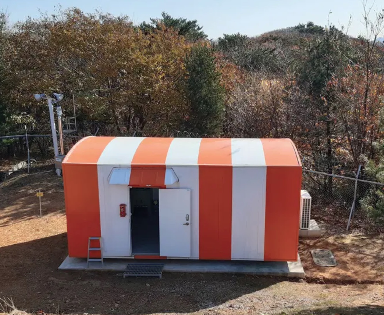
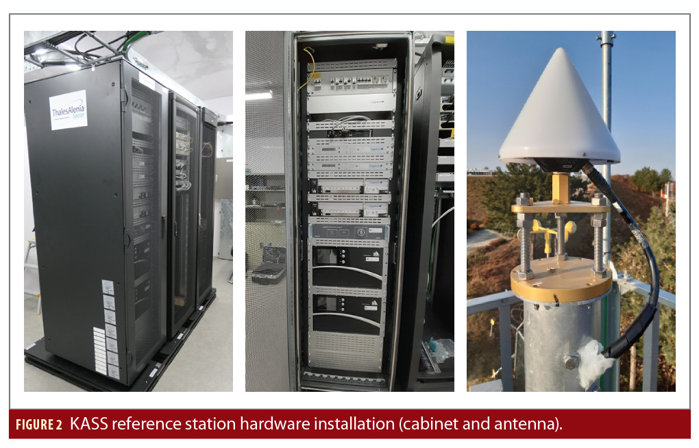
KASS system deployment began at the end of 2020 with the onsite installation of the system reference stations network. Figures 1 and 2 show the reference station installation details with the station shelter and the reference station hardware (KRS cabinet and antenna).
In parallel, the wide area network has been extensively tested and verified to allow continuous data transmission.
Since this first deployment step, data has been collected and Thales Alenia Space has undertaken the first performance analysis of real data.
This article presents the overall KASS system architecture as well as the first performance results using the deployed system under real conditions. These results are obtained through KRS real data collection and a replay on KASS test bench hosting fully representative KPS algorithms.
KASS Design and Architecture
The KASS system is the SBAS in Korea. A SBAS is a Global Navigation Satellite System (GNSS) augmentation system standardized under the International Convention on Civil Aviation SARPS Annex 10 [1], Volume 1, a document published and maintained by the International Civil Aviation Organization (ICAO). KASS will provide safety-critical services for civil aviation as well as an open service, usable by other forms of transportation and possibly other position, navigation and timing (PNT) applications.
The KASS system will provide improved GNSS navigation services for suitably equipped users in the defined service areas of the Republic of Korea by broadcasting a signal augmenting the U.S. Global Positioning System (GPS) Standard Positioning Service (SPS). The augmentation signal provides corrections of GPS satellite orbits and clocks and integrity bounds of orbit/clock residual errors, as well as corrections and integrity bounds for ionosphere delays. The augmentation signal will be broadcast by two GEO satellites and will be used by GPS/SBAS user equipment to compute a navigation solution.
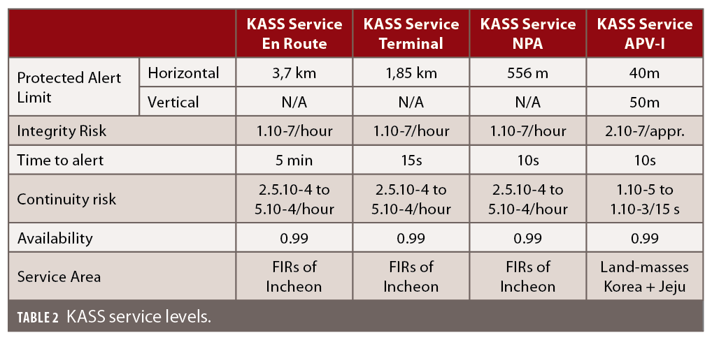
The KASS system is designed to ensure four safety-critical service levels:
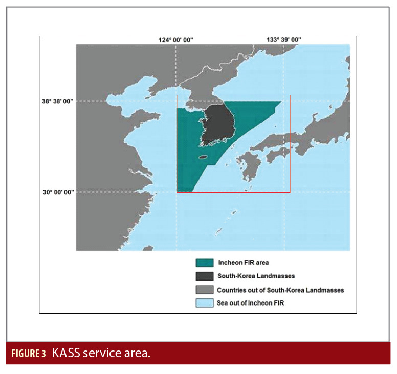
• En-Route over Incheon FIR area, flight segments after arrival at initial cruise altitude until the start of descent to the destination.
• Terminal over Incheon FIR area for descent from cruise to initial approach fix.
• NPA over Incheon FIR area, for non-precision approaches (NPA) in aviation, an instrument approach and landing that uses lateral guidance but does not use vertical guidance.
• APV-I over South Korea land masses (including Jeju Island), for precision approaches with vertical guidance. KASS will also provide open service over the Incheon FIR area.
Figure 3 shows KASS service areas.
The KASS system is designed to be a system-of-systems that performs these main functions:
• Collects GPS data at various locations in the Republic of Korea (and possibly in other states in the future).
• Computes corrections and associated integrity bounds from ranging measurements of GPS satellites in view of the KASS service area.
• Formats messages compliant with the SBAS user interface standardized in ICAO SARPS Annex 10 [1] and the RTCA MOPS 229 [2].
• Uplinks a signal carrying these messages to navigation payloads on the KASS GEOs.
• Broadcasts the signal to users after frequency-conversion to the L1 band.
Additional support functions are implemented:
• Wide area network between the KASS sites.
• Monitoring and control of the KASS elements.
• Support to KASS operations.
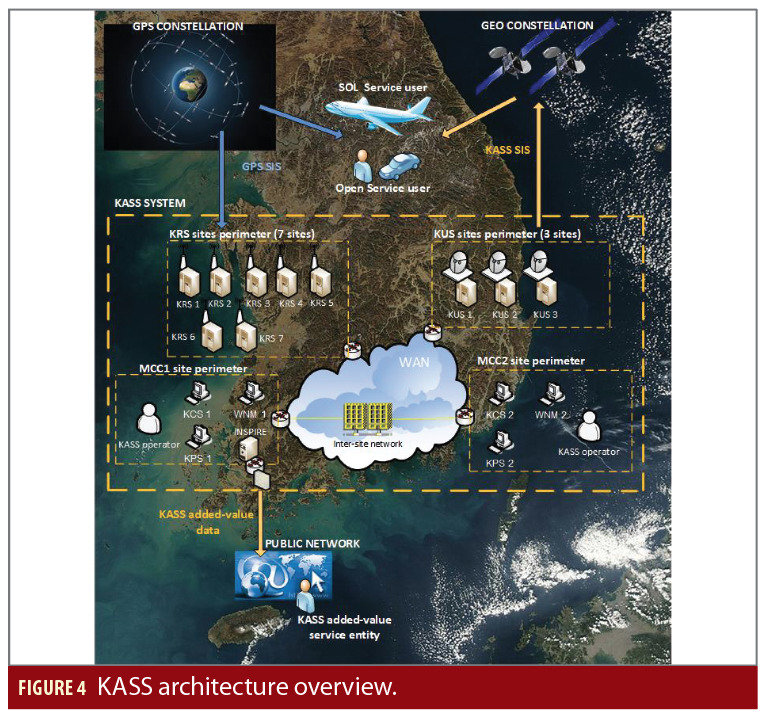
Main elements of the KASS architecture are:
• 7 KRS (reference stations) deployed on seven KRS sites.
• 2 KPS (processing units) and 2 KCS (monitoring and control units) deployed on the two main control center sites.
• 3 KUS (uplink stations) deployed on 2 KUS satellite broadcast sites.
• A wide area network ensuring inter-sites data exchanges.
Figure 4 shows the overall KASS architecture.
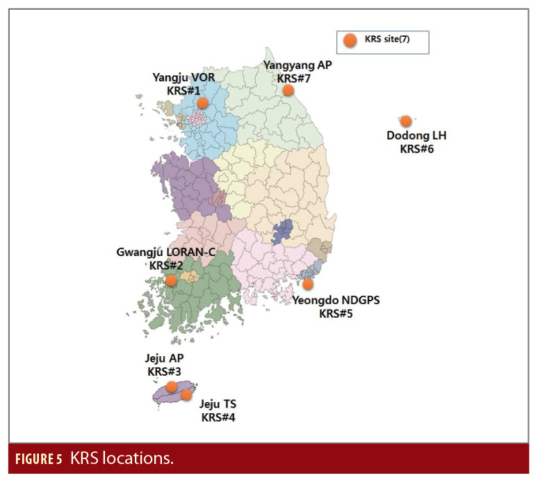
The KASS reference stations network was deployed at the end of 2020. Figure 5 shows the final KRS network locations over Korea land masses.
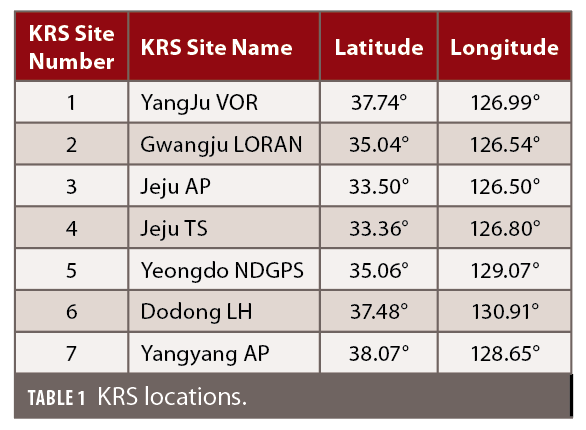
The KRS detailed site implementations are outlined in Table 1.
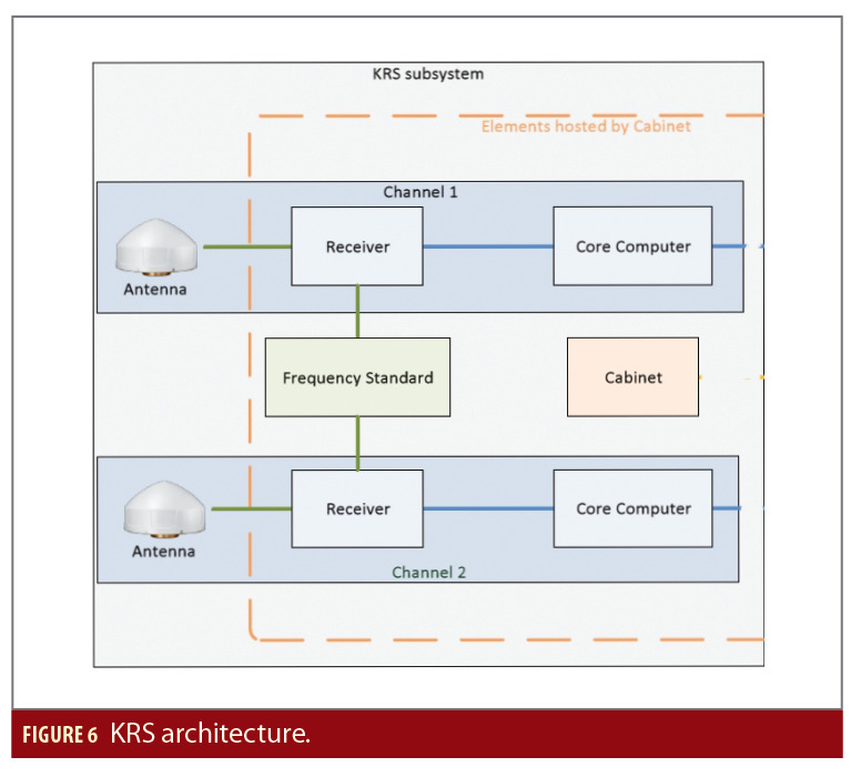
The KRS subsystem is composed of two independent channels, each one providing independent measurements to KPS-PS and KPS-CS. The KRS are based on NovAtel WAAS GIII receivers.
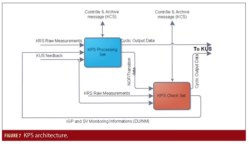
The KPS subsystem includes one processing set and one check set. The KPS processing set (KPS-PS) determines the user data information (corrections, confidence intervals, etc.) using GPS raw measurements from one channel of each KRS. The integrity of the information is checked by the KPS check set (KPS-CS) using independent data from the second KRS channel (independent receiver and antenna). The KPS transmits safety status information to the KUS to allow a possible switch by selecting a KPS to be used as the user data provider.
Key Performance Parameters
In the frame of the analysis, KASS system performances are evaluated to verify the main SBAS requirements.
Performance of a satellite navigation system are expressed through five criteria: accuracy, integrity, continuity, availability and time-to-alert (TTA).
The accuracy feature is the difference between the computed value and the actual value of the user position and time.
The integrity risk is the probability that an error, whatever the source, during the period of operation might result in a computed position error exceeding a maximum allowed value, called the alert limit, where the user is not informed of the error within the specific time-to-alert.
The alert limit is, for a given parameter measurement, the error tolerance not to be exceeded without issuing an alert. It is dependent on the flight phase, and each user is responsible for determining its own integrity in regard to this limit for a given operation phase following the information provided by the SBAS SIS.
The system TTA is the time an alarm condition occurs to the time the alarm is displayed in the cockpit. Time to detect the alarm condition is included as a component of integrity.
The continuity of service of a system is the capability of the system to perform its function without unscheduled interruptions during the intended operation (for example the landing phase of an aircraft). It is evaluated as the probability that from the moment the criteria of precision and integrity are completed at the beginning of an operation, they remain so for the duration.
Finally, the availability feature is the percentage of time when, over a certain geographical area, the criteria of accuracy, integrity and continuity are met.
The detailed KASS performance specifications are outlined in Table 2.
It must be noted that performance requirements include:
• The system performance in fault free conditions
• The system performance in front
of threats/feared events (FE) (GPS FE, KRS FE, Hardware FE, etc.)
This article only presents the KASS peformances in fault free conditions, in front of the first real data collection.
Performance Test Bench Description
The performance assessment is based on an engineering test bench that hosts the KASS KPS algorithms (both PS and CS). It is able to simulate end-to-end behavior of the KASS system.
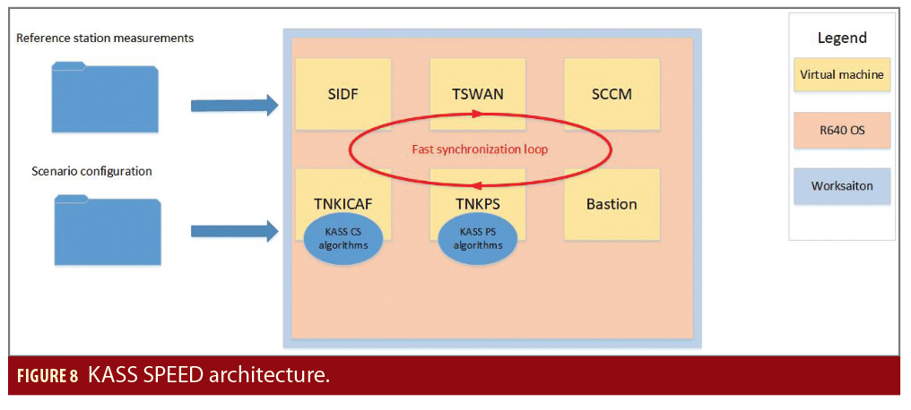
The KASS test bench solution is an evolution of the legacy EGNOS test bench (SPEED), using an optimized hardware architecture and virtual machines. This architecture is based on a single server that ensures:
• The use of KASS Processing set algorithms (KPS-PS prototype) based on Thales Alenia Space development, allowing the ability to monitor any internal data.
• The use of KASS Check set algorithms (KPS-CS prototype) based on IFEN company development, allowing the ability to monitor any internal data.
• The real time monitoring and control (RTMC) behavior of the KPS components that is managed by a hosting structure.
• The KASS network and uplink station emulation.
• The emulated reception of data from KRS and GEO satellites.
• The ability to process data in a fast mode (fast synchronization loop).
Figure 8 shows the SW component architecture overview. The KASS CS and PS algorithms are hosted respectively in TNKICAF and TNKPS SW components. The SIDF, TSWAN, SCCM SW and Bastion SW components manage the external interfaces and ensure the data flow exchange/control to simulate the system close loop.
Results and Discussion
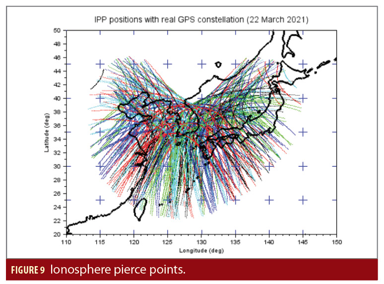
KASS is characterized by relatively small service areas and a concentrated KRS network over South Korea land masses, which constitute some challenging conditions in terms of satellite and ionosphere observability as shown in Figure 9.
The performance assessment was performed from March 20 to 24, 2021 (5 full days). This assessment is not fully representative of the final KASS performance because the real data collection for March 2021 has been limited to GPS raw measurements at high elevations (≥ 15°) defined by the KRS masking angle, whereas the KASS system is designed to allow GPS satellite tracking from 5° of elevation. KRS masking optimization activities will be handled in the frame of the system qualification.
The monitoring performance is mainly driven by the geographic surroundings of the antenna sites that are different for each station. The mountainous terrain constitutes challenging conditions for KASS, in terms of multipath and “clear horizon” obstacles.
Performance results are as follows:
• For March 22, 2021 when daily figures are considered. This is the middle day of the performance assessment period, and daily performances remain equivalent over the overall observation period.
• For the average of the five days when performance results are assessed from the user point of view.
Satellite Monitoring
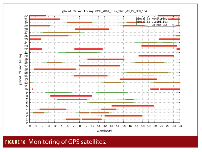
Figure 10 shows the monitoring of the GPS satellites by KASS on March 22, 2021.
The global monitoring performance is expected to represent about 85% of the maximal observability period (impact of data collection limited to elevation ≥15°).
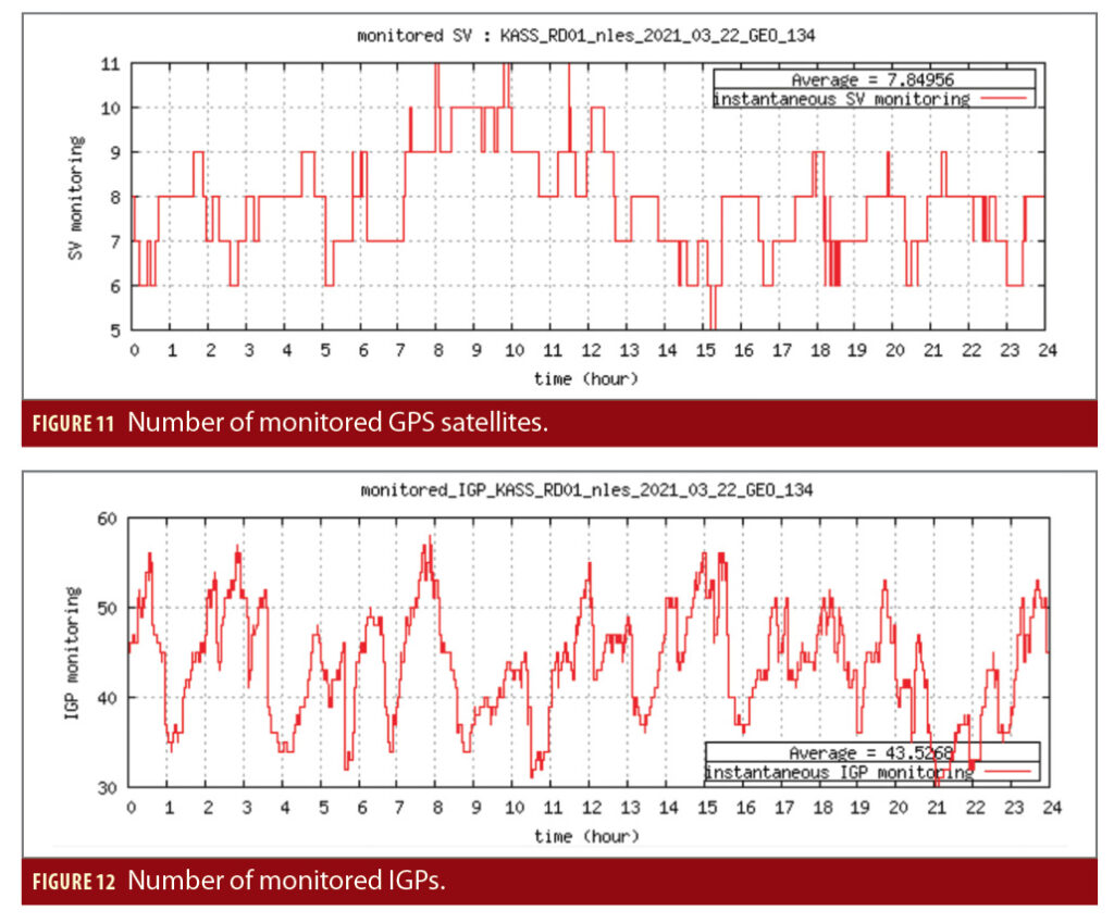
When displaying the number of GPS satellites monitored at the same time, the analysis shows that five to 11 satellites can be monitored simultaneously (Figure 11).
The KASS system ensures an average of more than seven monitored GPS satellites (around 7.8 satellites).
IGP Monitoring
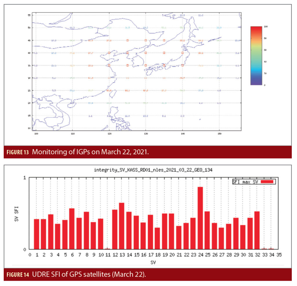
The IGP Mask is defined by 86 IGPs, more or less close to Korea land masses. The average number of 43 monitored IGPs is achieved on March 22, 2021. The monitoring of IGPs depends directly on the KRS locations and indirectly on IPP locations (Figure 13). The map presents the monitoring ratio for each IGP. Red squares correspond to 100% of monitoring.
The IGP monitoring is satisfactory with respect to the KRS network geometry (Figure 12), in particular at North where the IPP density is weaker (Figure 9). The GIVDs monitoring for the two IGPs at latitude 45° and longitudes 125° and 130° is ensured thanks to the internal model of the ionosphere of KPS-PS. The dynamic of the ionosphere captured at neighboring observation points(IPP) monitored by the system allows this monitoring with a sufficient confidence index.
Integrity from Satellite Corrections
To display the integrity of the satellite corrections for each GPS satellite, the notion of the UDRE Safety Index is used to assess the integrity margin. The UDRE Safety Index is defined as the ratio

The satellite residual error for the worst user location (SREW) is computed as the pseudorange error projection due to the remaining satellite ephemeris and clock errors after KASS corrections have been applied, for the worst user location of the relevant service area. The relevant service area corresponds to the intersection of the service area and of the monitored satellite footprint. The “true” SREW has been computed with the help of the precise GPS ephemerides provided by the International GNSS Service in sp3 format.
The user differential range error (UDRE) is defined in section A.4 of MOPS [2] and provided by the KPS Subsystem. For a given satellite, the user integrity is ensured as long as the UDRE SFI remains lower than 5.33.
The satellite SFI remains under the value of 1 for all GPS satellites on this day (Figure 14), which demonstrates the large integrity margin of the UDRE corrections broadcast by KASS.
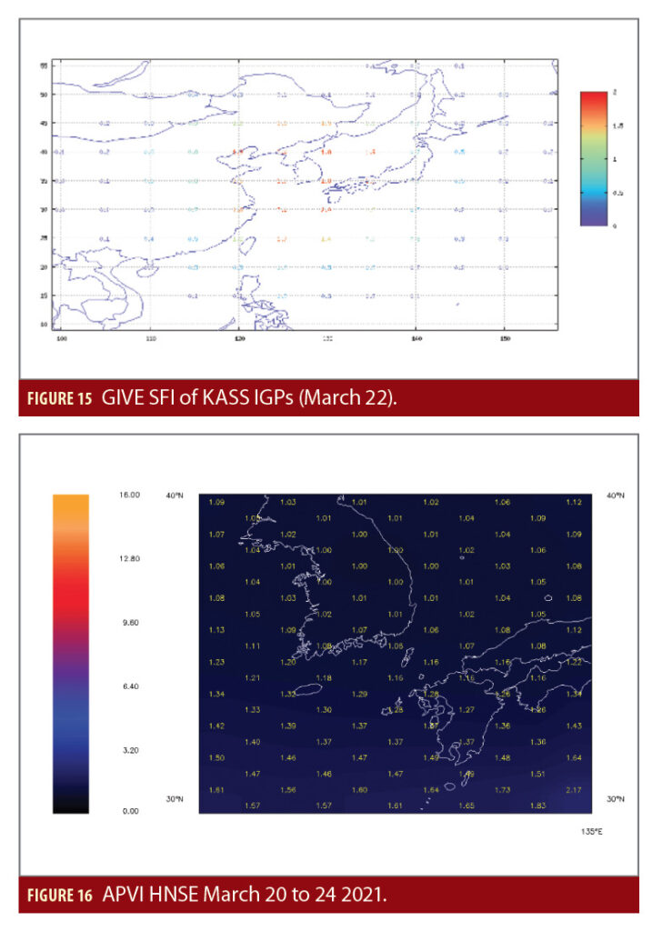
Integrity of Ionosphere Corrections
To display the integrity of the ionosphere corrections for each IGP, the notion of the GIVE Safety Index is used. The GIVE Safety Index is defined as the ratio

The GIVD Error is defined as the vertical pseudorange error at the considered IGP location, due to the remaining ionospheric delay after applying the GIVD corrections. The “true” GIVD error is computed thanks to precise real ionosphere conditions provided by the International GNSS Service in IONEX format.
The ionosphere SFI remains under the value of 2.0 for all IGPs on this day (Figure 15), which demonstrate the large integrity margin of the ionosphere corrections that KASS broadcasts.
Given the integrity assessment of satellites corrections (C) and of ionosphere corrections (D), the contribution of fault free conditions to the integrity risk is negligible with real data and is similar with the results obtained from synthetic scenarios used prior to the system deployment. Therefore, the integrity risk for APVI and the other KASS services is mainly induced from the impact probabilities of feared events.
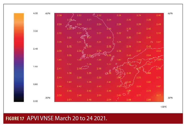
Accuracy at the User Level
The location of users is defined on a grid of longitudes from 124° to 134° East, and of latitudes from 30° to 39° North, with steps of 1°. The presentation is limited to the APVI Service level. The performances requirements for the other services (en route, terminal, NPA) are also fulfilled.
The horizontal and vertical navigation service errors (HNSE and VNSE) are presented in meters for each user position, for the APVI Service (at 95 percentile).
The accuracy performance demonstrates very good behavior of the KPS algorithms, correcting the GPS orbits, clocks and ionosphere with efficiency and high accuracy in vertical as well as horizontal axis (Figures 16 and 17).
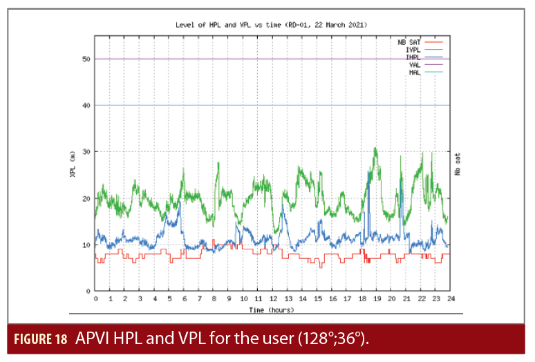
APVI Protection Levels at User Level
Figure 18 shows the APVI protection levels (HPL and VPL) achieved for a user located at [128° East in longitude; 36° North in latitude] (South Korea landmass center). The vertical alert limit (VAL) is 50 m and the horizontal alert limit (HAL) is 40 m for the APVI Service.
On March 22, 2021, protection levels show very good margin versus the APVI alert limits (HAL and VAL).
As expected, a high correlation exists between the rising/setting of GPS satellites and the HPL/VPL usable by safety-of-life users.
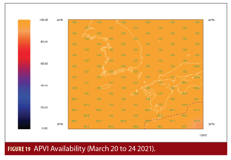
APVI Availability
The APVI service availability (Figure 19)is fully ensured over the complete service area. Some availability degradation is limited to the extreme South, outside any KASS service area, and without impact on performance.
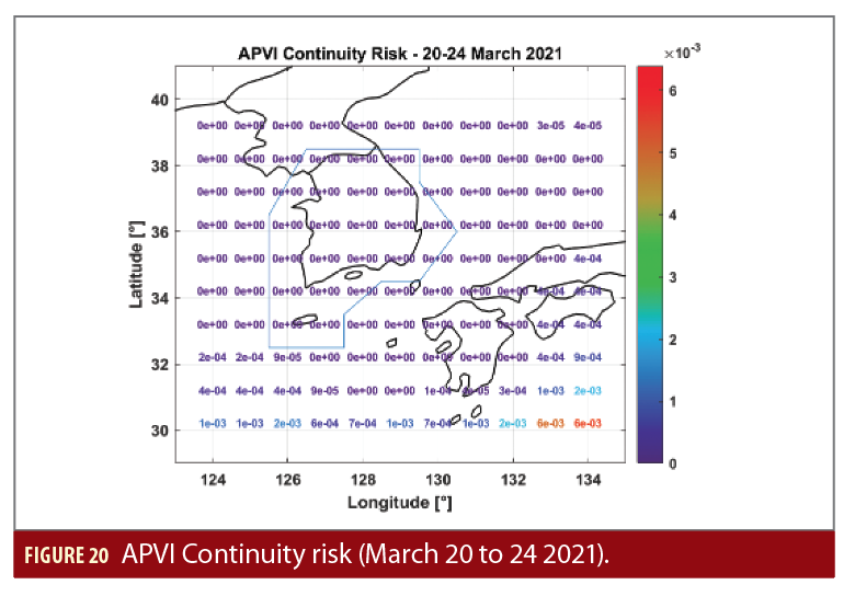
APVI Continuity Risk
The service continuity is fully ensured over the APVI service area (Korea Land Masses), when using real data from March 2021, in fault free conditions (Figure 20). Continuity degradations are only raised at south edges, with no impact on APVI performance.
The main contribution to the continuity risk in front of APVI and other KASS services correspond to the impact probabilities of feared events.
Conclusions
With a real data collection from March 20 to 24 2021, the KASS system performances in fault-free conditions and for APVI service level show very good levels of accuracy, continuity, integrity and availability.
These performances are achievedwith a data collection of GPS raw measurements being limited to satellite elevations higher than 15°.
The specific geometry of the KRS concentrated network, and the clear horizon around KRS sites (limited by the KRS masking angle), are well handled by the KPS navigation algorithms that ensure service performance during the five day period.


