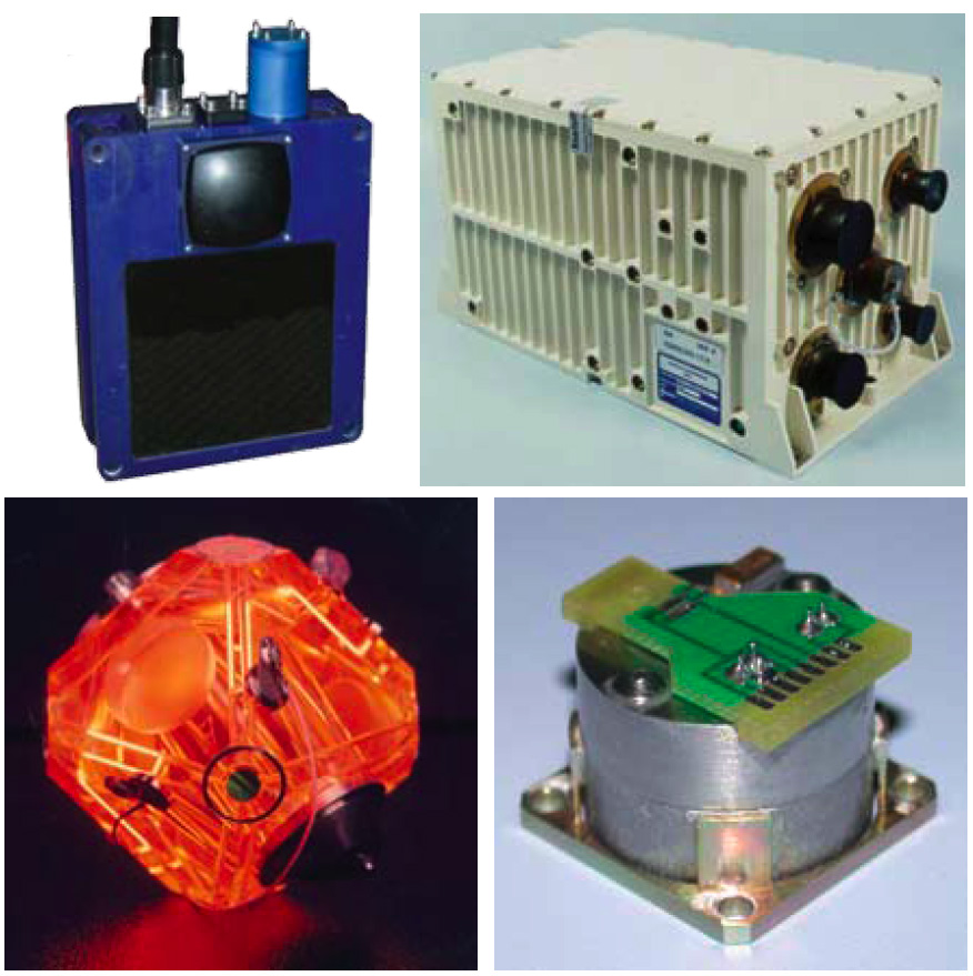
 Clockwise from top left: 3-D sonar system sonar head; Inertial navigation system sensor; pendulous force rebalanced accelerometer; three-axis MRLG.
 Staring into space on a clear night in the Mojave Desert yields a vista of stars so rich that words cannot begin to describe them. Within this vast field of view are the space elements of the Global Navigation Satellite System (GNSS).
Although these satellites are virtually invisible to the casual observer, GNSS provides autonomous, three dimensional (3-D) geospatial positioning with global coverage. While GNSS works in many regions on the Earth, it does not work in all areas.
Staring into space on a clear night in the Mojave Desert yields a vista of stars so rich that words cannot begin to describe them. Within this vast field of view are the space elements of the Global Navigation Satellite System (GNSS).
Although these satellites are virtually invisible to the casual observer, GNSS provides autonomous, three dimensional (3-D) geospatial positioning with global coverage. While GNSS works in many regions on the Earth, it does not work in all areas.
Like space, the Earth’s oceans are vast, covering most of our planet. Although GNSS is available to a ship sailing on the surface of the ocean, its signals are attenuated and ultimately lost to vehicles traveling beneath the surface.
To facilitate subsurface navigation, underwater vehicles typically obtain a series of GNSS position fixes prior to submerging. These position fixes are provided to an on-board inertial navigation system (INS) along with data from the other sensors, such as the fathometer, speed log, and Doppler sonar. As the vehicle submerges and GNSS signals are lost, the INS becomes the sole source of position information unless an underwater position fix can be acquired.
Until recently, obtaining a position fix while underwater was difficult. However, new 3-D sonar technology offers the capability to establish position fixes with accuracy comparable to that of GNSS. This technology brings advanced capabilities to many different operations that occur in underwater environments, including such activities as oil exploration, environmental remediation, and security-related applications.
This article provides an overview of the technology and its application for 3-D underwater mapping, precise navigation in littoral surface and subsurface environments, docking, pier and vessel hull surveys, mine and improvised explosive device (IED) detection, infrastructure surveys, and diver identification.
The Technologies
The proprietary 3-D sonar technology that we use provides an instantaneous 3-D image of the underwater environment. Maximizing system performance requires interfacing the 3-D sonar electronics with INS and GNSS technologies. This approach enables the 3-D sonar to accurately provide the geospatial position of an object of interest or, in the absence of GNSS, provide a position fix to the INS and generate a 3-D mosaic image of the surveyed object of interest.
The following sections offer an overview of the diverse technologies that are integrated to create a 3-D image or obtain a position fix.
3-D Sonar System. The 3-D sonar system is unlike conventional multi-beam or scanning sonar that typically uses postprocessing to combine scans in order to create a 3-D image. Rather than using a narrow fan of acoustic beams, the 3-D sonar system technology simultaneously forms more than 16,000 acoustic beams to fill a 3-D volume for each ping. This process is accomplished in real-time at a rate of up to 12 frames/pings per second.
The images provided by the 3-D sonar system, such as those shown in Figure 1 (at the top of this article), appear to be taken by an underwater camera, not sonar. With its rapid frame rate, the 3-D sonar system can capture moving objects, such as dolphins and divers, and display them in a format that compares to a live video.
The 3-D sonar system accepts real-time navigational data, including heading, pitch, roll, acceleration, position, and speed from the INS. This data enables each ping to produce a 3-D image with an accurate geospatial reference. Georeferenced ping data allows the creation of overlaid mosaic datasets adding each ping to the 3-D scene in real time to build an ultra-high-definition map on the fly, as shown in Figures 2 and 3.
Each output ping from the 3-D sonar system, shown in the inset photo (above right), ensonifies a 50×50-degree volume of water to a maximum range of approximately 150 meters. Phased-array technology is used in the planar receive array to form a large number of beams in both the horizontal and vertical directions. This allows range and target strength data to be acquired for each point on a grid that represents the volume being ensonified, as illustrated in Figure 4.
The 3-D sonar system’s transmit array forms 128 beams vertically and 128 horizontally; the receive array is composed of 48×48 channels. This configuration produces a 50×50-degree field of view, which is decomposed into 16,384 beams, each with a horizontal and vertical width of approximately 0.4 degrees. Standard 3-D sonar system performance specifications are outlined in Table 1.
The system’s sonar head houses the sonar projectors and the receive array panel. Beam-forming, focusing, and first-pass seabed detection are carried out in the head. Data is output from there over a copper connection cable to the data interface unit (DIU).
Power (24 VDC) for the sonar head is supplied via the same cable, as well as from the DIU. The 3-D sonar system’s physical specifications are outlined in Table 2 and its interface specifications, in Table 3.
Inertial Navigation System. Unlike the unique proprietary 3-D sonar system we used, many INS manufacturers and technologies are available. This article, however, focuses on the INS shown in the inset photo (above right). It integrates a three-axis monolithic ring laser gyro (MRLG) and a triad of pendulous force rebalanced accelerometers. The MRLG represents the latest in ring laser gyro (RLG) technology, which the manufacturer pioneered in the 1980s.
The INS can effectively collect data from many sources of position and velocity aids including GNSS receivers, Doppler velocity log and electromagnetic speed logs (EMS Logs) and depth sensors. These independent data sources are used in the INS software to aid system performance and bound inertial instrument drift. The integrated system design ensures real-time flow of navigational data, including heading, pitch, roll, acceleration, position, and ship speed.
Navigation System. While the 3-D sonar system is capable of producing a 3-D image with a single ping, it requires a precise navigation system to create an accurate 3-D mosaic like the one shown in Figure 5.
In addition to the 3-D sonar system and INS, the typical underwater inspection system (UIS) features two survey grade GNSS receivers, an above-water camera, a pole mount, a DIU, and a laptop.
The UIS is designed to be quickly mounted onto a variety of boats like the U.S. Navy autonomous test craft shown in this photo.
Mapping and Navigation
The geospatially referenced images provided by the sonar system enable us to produce real-time 3-D underwater maps. In addition, the coordinates from an object or a dataset can be used to obtain an accurate position fix.
With accurate position and attitude information from the INS, we can combine the underwater mosaic image with a mosaic image from the above-water camera, resulting in an all-encompassing view of the search area, as shown in Figure 6 and on the cover of this magazine.
Precise navigation in littoral sub-surface and surface environments is essential to the success of the warfighter with an INS typically serving as the core of a vessel’s navigation suite. The INS uses a suite of sensors to estimate the position of the vehicle, including a GNSS receiver that provides an absolute position fix.
In the absence of GNSS, the INS must rely on other sensors such as a fathometer, speed log, or Doppler sonar to dead-reckon (DR). Depending on the quality of the INS, the circular error probable rate (CEPR) of the distance traveled per hour can vary from less than 0.1 percent to greater than 0.5 percent. However, regular position fixes from the 3-D sonar could offer a CEP of 10 meters, facilitating precise navigation similar to that provided by GNSS.
We can use a variety of methods to obtain a position fix with the 3-D sonar system. One approach entails calculating the position of the vehicle with respect to a fixed underwater navigation aid, such as a buoy and chain.
Another approach involves using a 3-D feature extraction algorithm to provide continuous positional fixes, provided that sufficient features are present. Although there are many different 3-D feature extraction algorithms, the algorithm discussed in this article does not require that the area is previously mapped or surveyed. However, it does require that the initial position is known and sufficient subsurface features exist to grow a survey on the fly.
In other words, you start out with a frame of sonar data with recognizable features. Because you obtained this sonar data with an accurate position fix from GNSS, you have accurate locations for each attribute of the sonar data. Using this as your starting point, you can accurately estimate your subsequent position by comparing the features from frame to frame. Further, you can estimate the position of features in new frames from your now known position. This process creates a real-time survey.
Feature Extraction. Recently we used a 3-D feature extraction algorithm developed by J. N. Markiel (see Acknowledgments section) to generate position fixes from the 3-D sonar data. This algorithm, used in conjunction with the 3-D sonar, is not a replacement for GNSS; it will accumulate errors over time and cannot navigate indefinitely. However, when compared to the performance of an uncompensated INS, this approach provides clearly superior performance and significantly extends the time required between GNSS position fixes.
The algorithm consists of four modules: pixel classification, assessment of static / non-static condition, feature matching, and position/attitude determination.
Four modules comprise the feature-extraction algorithm and process, which need to accomplish three things:
- use the transition pixels to determine the edges of feature surfaces
- determine if those transitional regions are static or non-static
- use static pixel regions to trilaterate position between two coordinate frames of reference.
The first module segregates the pixels based upon the eigenvector signatures of linear based features. Pixels with similar signatures are merged to create features; the edges of these features are converted into a binary image to enable rapid evaluation and processing of feature edges in later modules.
A key innovation is the use of statistics drawn from the image data to drive thresholding heuristics. The two images are treated as samples drawn from a larger, unknown distribution of range values and compared to verify the condition of homogeneity.
After verification, the heuristics are dynamically adjusted based upon changes to the distribution of range values. Because the algorithm does not rely on a priori values to determine the segmentation characteristics, the program can operate on an automated basis.
The second module converts the previous image to the same coordinate frame as the current image. This is accomplished in two steps. First, information from the inertial system provides an initial estimate of the necessary adjustment. This initial transformation incorporates errors inherent to the inertial system and must be refined. An additional innovation is the implementation of a RANSAC-style approach to finalize the transformation.
The range of solution space is constrained by the error information from the initial inertial data, which enables the algorithm to determine the solution based exclusively upon the sensor data. After the quaternion-based transformation of the previous image is complete, the image is motion-compensated to adjust for pixels that are not relevant to the transformed image due to the change in pose and associated change in field of view.
The algorithm then uses a small window to compare transition pixel signatures for motion determination. The size of the search window is based upon reported uncertainty in position and is therefore derived from the process information, rather than defined on an a priori basis.
A key issue in comparing imagery is the ability to match features between images such as those in two sequential sonar datasets. The problem of locating n features from the initial image amongst m features in the current image is not a simple exercise in transformation, and errors can occur in the process.
There is a possibility that the transformation to a common coordinate frame has introduced errors to the feature position(s). There is also no guarantee that the features from the first image will be present in the second image or that the matches will be unique.
The third module of the algorithm resolves the challenge of feature matching by comparing eigenvector signatures for feature edge pixels in each image. The algorithm again leverages statistics derived from the image to enable an automated, heuristically based evaluation of matching features.
Using the sonar-based data, the fourth module triangulates the position of the mobile unit based upon the known ranges to matched features. The information is then returned to the integrated system to update the inertial system.
This aspect of the program directly emulates a traditional GPS/INS tightly coupled integration schema with two important variations. First, the feature-based, triangulated position is employed in the place of a GPS fix, and, secondly, the covariance matrix for the corrected position is updated at each iteration. This reflects the variable uncertainty due to differences in image-matching results.
After updating, the INS returns coarse information for the relative change in pose during the acquisition of the next image, and the algorithm initiates a fresh sequence of feature matching and position evaluation. Figures 7, 8, and 9 show the results of applying this algorithm to 3-D sonar and INS data obtained and recorded in the Panama Canal.
For this example, the dual survey-grade GPS–aided INS solutions were available based upon the processed solution. The INS position and attitude data was used to support the 3-D sonar feature extraction algorithm in providing the “coarse” estimate of position/attitude change that enabled constrained searches for static and matching features. In the figures, the blue crosses reflect estimates of vehicle position.
Docking with the Aid of 3-D Sonar. Docking an underwater vehicle can present some unique challenges and be time consuming. The 3-D images from the sonar system allow the docking process to be monitored in real-time. This capability reduces the time required for the docking process and the risks of damaging the vehicles.
The 3-D sonar system has been used to monitor the docking of an underwater buoy with a ship’s mating cone. The 3-D sonar images provide the relative position of the buoy, as shown in Figure 10. This information is used to position the ship directly over the buoy prior to pulling the buoy in.
When the mating cone is positioned directly over the buoy, as shown in Figure 11, the pull-in process begins. During the pull-in process, the buoy is continuously monitored, as shown in Figure 12.
Port and Harbor Security
Ports and harbors are typically busy places with ships moving in and out in a coordinated fashion to minimize their time at the pier and maximize the time for moving cargo. Holding up a single ship, let alone many ships, is expensive to everyone involved — including the consumer who buys products shipped to and from various ports around the world.
The dynamic environment associated with ports and harbors presents many challenges to security. This section of the article focuses on security-related applications in these sensitive locations using the 3-D sonar system.
Pier Surveys. An efficiently operating port or harbor has equipment and cargo moving at all times. Taking time to survey a pier, vessel hull, underwater pipeline, or the base of a bridge can affect the efficiency of the port, causing delays and increasing cost. Many ports rely on the 3-D sonar to minimize the time required for these surveys.
From above the water, a pier at a busy port may appear to look like a road that extends into the water. The person standing on top of the pier is unaware of the numerous pilings holding the pier in place and supporting the weight of the machinery and cargo that is loaded and unloaded.
The pilings of a pier are typically arranged in rows that span the length of the pier like those shown in Figure 13. The number of pilings depends on the length and width of the pier, with large piers supported by hundreds of pilings.
Pier supports can be very difficult to survey quickly with conventional multi-beam or scanning sonars because these sensors cannot see behind the first row of pilings. However, the 3-D sonar system’s phased-array technology allows an operator to see virtually all the pilings in a single pass, as illustrated in Figure 14.
This capability permits rapid pier surveys. The survey data can also be archived for comparison in future surveys where change detection software can quickly compare the surveys and alert the operator to differences.
Vessel Hull Surveys. On any given day, a variety of vessels will move in or out of a busy port or harbor. Like automobiles and trucks, the variety of vessels can range from a small motorboat to a super tanker and every size in between. Unlike an automobile or truck, however, a ship is not visible to the unaided eye from top to bottom.
Depending on the amount of cargo the ship is carrying, a large portion of the ship is typically underwater and invisible to the casual observer. In that respect, a fully loaded super tanker is similar to an iceberg.
A ship that is not moving cargo is not making money. To maximize a ship’s operational time, hull inspections to detect damage, deterioration, or weakness need to be conducted as quickly as possible and may need to take place in a variety of locations. A hull survey may be conducted while the ship is moored alongside a pier, as shown in the top of Figure 15, or it may be accomplished while the ship is anchored in the harbor, as shown in the bottom of the figure.
The 3-D real-time capabilities of the sonar system allow an operator to inspect critical components of the ship’s drive train, such as the propeller, as shown in Figure 16. The operator can also inspect the hull of the ship for damage or objects that may have been attached to it.
To facilitate quick analysis of any object found on the hull, the operator can make accurate measurements, as shown in Figure 17. Using the mouse, the operator can measure the length, width, height, or diameter of any object in view.
Infrastructure Surveys. Many infrastructure components that support a busy port or harbor are located underwater. Some of these components such as the base of a bridge, as shown in Figure 18, or an underwater pipeline, as shown in Figure 19, need to be periodically surveyed.
The 3-D sonar system generates high-resolution images that allow inspections to happen in real time. Change detection software can compare archived survey data with the current survey to alert the operator of significant differences.
Mine and IED Detection. The U.S. Navy’s Unmanned Undersea Vehicle (UUV) 2004 Master Plan states that the growing use of unmanned systems – air, surface, ground, and underwater – is continually demonstrating new possibilities that can assist our naval forces in maintaining maritime superiority around the world. Furthermore, these unmanned systems help to keep the warfighter out of harms way.
Although many unmanned systems are in use throughout the U.S. Navy, this article focuses solely on a 3-D sonar mission module for unmanned surface vehicles (USV). A variety of USVs are currently in development.
The USV shown in this photo was designed to accept modular payloads for a wide range of missions. This type of USV has horsepower, speed, and size advantages over an UUV. Its diesel engines can propel the craft at speeds in excess of 30 knots. This horsepower advantage allows operation in the strongest currents and high transit speeds to the operational area.
In comparison, a UUV, similar to the one pictured here, is typically battery-powered and designed for low-speed operation. These vehicles are not capable of operating in strong currents such as those typically found at the entrance to a port or harbor.
The payload capacity of a UUV is also significantly less than a USV and cannot easily accept payloads that are mounted externally to the superstructure. However, a USV, such as the one shown here, easily accommodates the external pole-mounted 3-D real-time sonar system.
3-D Mission Module
UrsaNav and the manufacturer of the 3-D sonar system have developed a preliminary design for a state-of-the-art, high-resolution sonar mission module. This system features a pair of retractable 3-D sonar arrays, with each array employing three 3-D sonar modules.
This system is intended for channel, port, and harbor security and surveillance operations. Capable of operating at six knots, the 3-D sonar system can inspect an area of up to a square nautical mile in a single hour.
The mission module features a pair of retractable 3-D sonar arrays; each array employing three 3-D sonar modules, as shown in Figure 20. Each array has forward-looking, outward-looking, and downward-looking modules, as shown in Figure 21. Together they create a coverage area forward, out, and down with up to a 150-meter radius, as shown in Figure 22.
The port and starboard arrays are designed so that the forward-looking modules provide overlapping coverage from across the bow to about 20 degrees abaft each beam, as shown in Figure 23.
As the USV moves forward through the search area, images from each sonar array are stitched together to create a single 3-D mosaic image. This mosaic image is essentially a, 300-meter in diameter, half-cylinder 3-D model of the water column along the ship’s track.
The 3-D sonar system can accurately measure the geospatial position of an underwater object, as shown in Figure 24. A buoy and chain is displayed in the image, along with the latitude, longitude, and altitude of the location where the chain attaches to the bottom of the buoy. This buoy is located near a canal bank in the Panama Canal, as shown in Figure 25.
Object Identification
The 3-D images produced by the sonar system enable easy detection and classification of suspicious objects, such as mines and improvised explosive devices (IED), or presumably benign objects, such as divers or aquatic animals.
A mine-like object with a 160-millimeter diameter, as shown in Figure 26, is attached to the piling of a pier. The same object is shown attached to the hull of a ship, as shown in Figure 27.
To further assist in classification, the 3-D sonar system also has the ability to accurately measure an object of interest. Figure 28 shows two tires positioned on the bottom of a harbor. In this screen capture, the operator is measuring the diameter of the tire on the left.
Being able to tell the difference between a diver and a marine mammal, such as a dolphin, is challenging. Both objects move through the water and, because they are primarily made up of water, they do not produce sharp acoustic reflections. However, unlike the dolphin, divers inhale and exhale underwater; releasing a gas plume or burst of air bubbles with every breath, as are clearly visible in Figure 29.
The system enables reliable diver identification because it can capture up to 12 frames of 3-D sonar data per second and produce a movie-like image that allows the operator to make a quick and intuitive decision. Figure 30 shows five frames of 3-D sonar images that capture three dolphins swimming across the sonar system’s field of view.
Summary
UrsaNav, Inc. and the manufacturer of the 3-D sonar system are working together to integrate the system’s unique, real-time, 3-D sonar capabilities into many different applications, including underwater mapping, precise navigation in littoral surface and subsurface environments; docking, pier and vessel hull surveys; mine and IED detection, infrastructure surveys, and diver identification. Together, the companies are bringing advanced capabilities to many different operations that transpire in underwater environments.
Acknowledgments
I would like to express my deepest appreciation to the following for contributing their invaluable subject matter expertise and/or findings and images from applicable studies to this article:
Rich Webb is a principal engineer at UrsaNav, providing engineering support for U. S. Navy, U. S. Coast Guard, and foreign military shipboard electronics systems. He has supported naval electronic programs for nearly twenty years since leaving the U. S. Navy submarine force.
J.N. (Nikki) Markiel is a doctoral candidate in geodetic science at The Ohio State University. She is currently employed with the U.S. Department of Defense as a Geophysical Scientist while finalizing her dissertation on 3-D feature-based navigation algorithms. Her research interests include utilization of geo-information for disaster planning, automated/semi-automated mapping methods, navigation in GPS-challenged environments, and remote sensing of volcanic activity.
Blair Cunningham is the chief technology officer of CodaOctopus Group, Inc. and senior vice president of CodaOctopus Products Ltd. He has more than 20 years of commercial experience in software and network technologies, providing solutions for public companies. He currently leads all R&D activities at Coda Octopus with primary responsibility for developing the Echoscope and cutting-edge UIS-based solutions.
Rolf Kahrs Hansen has been working for Omnitech AS (from 2002 CodaOctopus Omnitech AS) on the development of the EchoScope real-time 3-D sonar. His research interests include sensors, acoustic transducers, and acoustic signal processing. He holds several patents within 3-D sonar and sonar signal processing.
Donald J. Weber is a senior principal engineer with Kearfott Corp. Guidance & Navigation Division. He participated in the development of inertial navigation Systems utilizing Tuned Rotor Gyroscope and Ring Laser Gyroscope technologies. He also contributed to the addition of various velocity aids (including Doppler velocity log) and GPS aiding to the inertial navigation system architecture by way of multi-state Kalman filter technology.
Robert Weingaertner is a project engineer in the System Engineering Department of the Systems Development Directorate, Kearfott Corporation Guidance & Navigation Division He has 34 years experience in the inertial navigation field, and is currently the engineering manager for the unmanned air vehicles (UAV’s) product line.
Michael P. Agor is a business development manager for CodaOctopus Americas. He served as an officer in the U.S. Navy for more than two decades, providing intelligence, operations planning, and undersea warfare support. He trained and certified deploying carrier battle and amphibious ready groups.
