Working Papers explore the technical and scientific themes that underpin GNSS programs and applications. This regular column is coordinated by Prof. Dr.-Ing. Günter Hein, head of Europe’s Galileo Operations and Evolution.
With the support of the European Space Agency (ESA), a European team designed a frequency- and time-transfer process and validated its performance in a complex navigation test bed. This two-way time-transfer technology took advantage of the following:
- the existing GMSSS (Ground Mission Segment to Space Segment) uplink tracking, telemetry, and control (TT&C) ground station of the Galileo system
- an ad hoc design of the geostationary satellite (GEO) navigation payload which included the possibility of eliminating the onboard atomic clock reference through the use of an onboard oven-controlled crystal oscillator (OCXO) whose fine frequency tuning is controlled from a long onboard-to-ground delay locked loop (DLL),
- the tracking accuracy provided by enhanced correction capability provided by using a downlink Galileo navigation signal generation unit (NSGU) based on the latest generation of Galileo signals, which employ a binary offset carrier (BOC) modulation.
As discussed in this article, the measured clock synchronization performance can be summarized by the following metrics: 325 picoseconds (1σ) standard deviation of one pulse per second (1PPS), onboard-to-ground error (time transfer) and an Allan Deviation better than 10-12 over an averaging time of 180 seconds (frequency transfer). This performance would enable an order of magnitude improvement in accuracy of the current European Geostationary Navigation Overlay Service (EGNOS) specification for the time offset error between the system’s GEO time scale (GEO Time) and the EGNOS Network Time (ENT) at 3 σ.
Current and Future SBAS Architectures
A long, on-going technical discussion has taken place about what the next generation of satellite-based augmentation systems (SBAS) should be in light of the evolution of the new GNSS constellation systems and the maintenance cost of the complex ground synchronization layer of first-generation SBAS systems.
The original shortcut of using the transparent approach portrayed in Figure 1 was conceived as a very ergonomic solution because the payload impact was very low in terms of power and weight. (Both EGNOS and the U.S. Wide Area Augmentation System, or WAAS, are currently based on this approach). In this context, “transparent” means that the downlink SBAS signal is not generated on board the satellite and the payload segment will only amplify and filter, with up- and down-conversion at the RF front end of the payload, the ground-generated SBAS signal.
This operating mode shown in Figure 1 was usually conceived as an add-on, piggy-back solution, to be used on a standard GEO communication payload This approach was certainly viewed as a good trade-off back in the early and mid-1990s when those systems were conceived, because it minimized the SBAS payload cost of being hosted on a standard telecommunication satellite.
In addition to simply broadcasting wide area corrections, a GEO satellite capable of providing a ranging service can clearly bring added value to the SBAS system performance as implemented, for example, in the WAAS system. Also, the accuracy of the corrections could benefit from the use of new SBAS architectures in which the GEO Time of a set of GEO SBAS payloads could be closely controlled and synchronized.
With the purely transparent approach, a major difficulty in using the SBAS ranging signals, or defining synchronous payload times, arises from various problems. These include a large group-delay wandering of the fully analog onboard signal path and difficulty maintaining the code/carrier coherence due to the onboard L-band downlink and uplink synthesizers. (In the absence of any clock reference synchronization, these are de facto asynchronous with respect to the reference clock in the navigation land Earth stations, or NLES, that serve as ground transmitters for the current EGNOS system).
The issue is further exacerbated considering that the existing GEO SBAS systems typically use more than one satellite to cover the regional area, thereby making it challenging to define a very accurate common synchronous time for GEO space vehicles (SVs). (EGNOS for Europe and North Africa coverage originally planned the use of three GEO SVs and currently is using only two of them)
A certain level of mitigation of the aforementioned issues could be achieved using the “regenerative” approach portrayed in Figure 2. Here, “regenerative” means that the carrier reference clock is regenerated as a quasi-synchronous replica of the ground clock, allowing the code-carrier coherency losses to be reduced.
With this system architecture, an onboard 10.23-megahertz reference clock could be extracted by means of an add-on navigation uplink MISsion RECeiver (MISREC) responsible for synchronizing the incoming symbol carrier through its phase locked loop (PLL). This would allow, to a certain extent, a sort of feed-forward, one-way carrier synchronization whose performance should depend on a mandatory controlled de-embedding of the contribution of the GEO-estimated Doppler from the recovered carrier reference.
Even in this case, the synchronization performances were expected to be much lower than a real two-way frequency transfer. Moreover, the large group delay variation due to the wandering in time (ageing) and temperature of the downlink and uplink analog electronics did not have any way to be controlled by design (as in a generative approach which allows separating the uplink and downlink contribution). Nor could this be controlled by onboard monitoring, given the completely analog payload structure that does not allow digital monitoring and compensating of the group delay (GD) variations.
Most relevant is the fact that both of the aforementioned solutions (transparent and regenerative) have issues related to the integrity of the navigation message received by the GEO payload and broadcasted to the user segment. The currently available strategy for SBAS transparent (or regenerative) approaches is to perform an integrity check of the navigation message uplinked from the NLES with the same message being received by the ground control stations on the downlink. However, the navigation message integrity check being performed on the ground implies that the corresponding counteraction of broadcasting a specific alert message, in the case of round trip errors, is not instantaneous (resulting in limitation of the time-to-alarm actuation).
Ultimately, there is no possible way of preventing the broadcasting of a misleading message with the SBAS systems presented in Figures 1 and 2 except by switching off the SBAS payload via a remote telecommunication link from the ground, which ultimately leads to a loss of availability for the augmentation service. A brute-force solution for guaranteeing synchronized and accurate broadcasting of ranging signals by a GEO, high Earth orbit (HEO), or inclined geosynchronous orbit (IGSO) SV is to imitate a standard navigation MEO SV reusing all the existing middle Earth orbit (MEO) payload hardware as shown in Figure 3.
This approach has the inconveniences of poorly using the potential associated with the currently available time and frequency transfer technology, increasing the payload hardware cost due to the need for an onboard atomic clock in the clock monitoring and control unit (CMCU) with the associated redundancy scheme (as described in the article by D. Felbach et alia listed in Additional Resources), and reducing the navigation payload mean time to failure (MTTF) due to the limitations of the atomic clock in maintaining its frequency stability and accuracy for an extended number of years.
New Approaches to Implementing SBAS Payload Architectures
An initial innovative effort to find an optimized solution to these issues, at least for possibly using GEO or HEO signals of a generative payload for ranging and increased availability, came from the Japanese Quasi-Zenith Satellite System (QZSS). The QZSS space segment consists of three SVs placed in periodic highly elliptical orbit. The perigee altitude is about 32,000 kilometers and the apogee altitude, about 40,000 kilometers. All QZSS satellites will pass over the same ground track. The QZSS system was designed so that at least one SV out of three available would always be present near zenith over Japan.
Given its orbit, each satellite appears almost overhead most of the time (i.e., more than 12 hours a day with an elevation above 70 degrees). This gives rise to the term “Quasi-Zenith.” As for controlling the group delay wandering and the code/carrier coherency on board, despite the intrinsic advantage of the regenerative payload approach vis-a-vis the transparent one, neither of the first two architectures (transparent and regenerative) presents the advantages of the generative approach.
However, using a generative payload with an atomic clock on board (as shown in Figure 3) is not efficient in terms of recurrent cost, weight, and power consumption compared to the existing transparent implementation. Additionally, its MTTF would always be limited compared to the analog transparent payload counterpart, or to a generative approach, with an OXCO on board.
Therefore, current design/implementation trends for regional augmentation satellites sought to take advantage of the fact that:
- a GEO SV has constant visibility from a ground control station, optimally placed in the regional coverage area, and
- a GEO SV Doppler dynamic is quite limited (also compared to the HEO of the QZSS system) reducing the Doppler shift effect in the onboard clock’s control loop.
This led authorities (such as Japan) to fly a quite stable OCXO controlled from a ground station on their satellites, with a very accurate, long-loop (onboard to ground) frequency and time transfer process.
For these reasons Space Engineering decided to explore the possibility of implementing an improved version (with respect to that implemented in the QZSS system) of the generative SBAS payload design with an OCXO on board (Figure 4). In this system, the OCXO frequency and phase alignment to the ground reference atomic clock is precisely controlled from the ground as in the Japanese QZSS system. Therefore, a real navigation-payload proof of concept has been designed, taking into consideration the compatibility with — and actually enhanced with respect to — the Galileo MEO payload as regards the uplink and downlink signaling.
With respect to an NSGU, the EGNOS Regenerative Payload (ERP) only needs to be augmented with on-board SBAS signal generation (Galileo-plus-SBAS dual-frequency downlink signaling), in addition to the OCXO synchronization control module. Additional MISREC firmware modification should also be ported from the ERP design to enable the ERP system payload implementation based on the reuse of Galileo full operational capability (FOC) space-qualified mission receivers.
ERP System Innovative Aspects Compared to QZSS
The proposed architecture for ERP time keeping is quite innovative even with respect to the only existing worldwide navigation application where an OCXO was first flown in a SV suitable for navigation signal broadcasting, i.e., the QZSS.
The innovative aspects of the ERP (which is the short name of the ESA contract financing this study) stem from the following considerations regarding the QZSS implementation design choices:
- The QZSS system actually modified the uplink signaling providing an uplink CDMA signal (equivalent to the GMSSS uplink signal used in ERP), with the carrier frequency being Doppler-compensated on the ground, i.e., with a time variable frequency offset profile steered by the uplink TT&C modulator. (For details, see the article by M. Fukui et alia in Additional Resources.) For the QZSS-equivalent MISREC onboard receiver, the net effect would be that of receiving a signal with almost null Doppler.
- The QZSS master control station (MCS) would keep two replicas of the QZSS time reference — one being the equivalent of the ENT, that is, the QZSS reference time steered to GPS system time. The other replica would always remain tied to the QZSS time reference, but be time phase–shifted in anticipation of the long delay locked loop–estimated uplink delay time. This implies that the QZSS equivalent MISREC on-board receiver would demodulate a CDMA ranging signal with almost zero delay (i.e., that it would already be aligned with the QZSS time reference). However, the two aforementioned QZSS design implementation choices have the following drawbacks:
- The QZSS approach implies that for each augmentation SV a separate transmitted signal replica should be handled by the MCS, which would bring increased costs for the necessary digital and RF hardware as well as the expense of calibration maintenance. (EGNOS initially planned the use of three GEO SVs.) The costs would be avoided by using a single TT&C modulator with different spreading codes as proposed for the ERP system.
- The uplink TT&C station could not be a standard TT&C because of the accurate frequency and time-steering agility required for the QZSS system. For the ERP implementation, the same GMSSS control station used for Galileo MEO uplink message control could be fully reused.
- The accuracy of the QZSS Doppler compensation, and therefore of the on-board 1PPS synchronization, will also depend on the analog performance of the uplink and its capability to preserve and accurately steer the Doppler profile estimated and injected from the ground control loop. (For the same class of OCXO device, in the ERP system the clock control precision is determined only by the accuracy of the digital algorithm as implemented.)
- The accuracy of the onboard 1PPS phase alignment with respect to that on the ground would depend on the accuracy of the phase-delay technology used on the ground segment for finely controlling the uplink delay.
- Finally, nulling the uplink Doppler would become vastly more complicated using the uplink carrier-phase ranging measurement to increase the accuracy of the time-keeping system. This would occur because in the multi-frequency uplink signaling mode — even in the most complex triple-carrier ambiguity resolution approaches — the carrier ambiguity resolution algorithms reveal convergence issues when applied to propagation channels with zero or near-zero Doppler shift. (This factor has not yet been addressed and solved in the technical literature or applications).
Although the Japanese should be given the credit of having first pioneered the concept of flying a navigation reference OCXO, these limitations of QZSS drove the ERP system architecture design toward a different and improved solution.
Validation Test Bed for ERP Time-Keeping
Figure 5 provides a schematic representation of the ERP test bed architecture. All the ground and payload equipment is represented with real hardware devices operating in real time so that any test configuration could be operated for an indefinite period of time. The test-bed architecture can also validate an SBAS user segment with third-party, real-time receivers capturing signals in space (SIS) and mixing them with virtual GEO RF signals propagated by the test bed.
This real-time test bed is suitable for assessing any frequency and time transfer performance, including emulation of transparent, regenerative, or generative SBAS payloads. It has this capability thanks to a single, fully reconfigurable COTS software defined radio (SDR) hardware platform.
The ERP test bed is also conceived to be interfaced with the ESA Support Platform for EGNOS Evolutions & Demonstrations (SPEED) test bed where the new or current correction algorithms could be executed and validated in real time. These could then be virtually uplinked and broadcast employing the ERP test bed with the generative approach so as to characterize the ERP test bed’s performance improvements for the user segment operating any third-party user SBAS receivers.
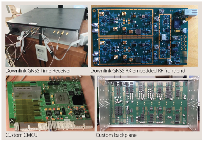
The overall test bed shown in the accompanying photo is quite compact, due to the reduced form factor of the COTS hardware platforms (all three-unit racks, i.e., 10 by 16 centimeters). The test bed can implement the entire digital and RF processing and synthesis of all the segments involved in an SBAS system of arbitrary complexity, in a six-unit 19-inch sub-rack (colored segment of left side of Figure 6).
The downlink ground controller timing receiver (TRX) is a triple-channel, dual-carrier GNSS receiver in a two-unit (2U), 19-inch assembling case built from the same SDR board described earlier and a dual-carrier, antenna-ready GNSS RF front end down converter. Two custom hardware board designs have also been developed, manufactured, and successfully tested. The first is the CMCU board hosting the onboard OCXO and its fine frequency controller. The second board is a custom 6U 19-inch backplane board designed to mechanically and electrically connect all the test bed boards within the 6U sub-rack. Accompanying photos (see inset photo, above right) show the ground controller time receiver and its various components.
Performance Achieved by ERP Time Synchronization
The equipment designed for the ERP test bed uses state-of-the-art hardware and real-time digital signal processing. Just to give a measured figure of merit of the overall accuracy (hardware plus channel emulator and demodulator algorithms) of the ERP test bed, we have compared the downlink GNSS ground receiver pseudorange (PR) with the reference trajectory of the EGNOS PRN 120 SV expressed in floating point. This reference trajectory was, of course, controlling the channel emulator during the test execution. Figure 7 shows the layout of the test bed for this calibration test. This configuration is synchronous and basically noiseless so as to achieve the highest-accuracy boundary performance.
In this test, the interaction of the test bed orbital propagator (OP) with the real-time hardware — composed of the NSGU, frequency up-converter unit (FUU), downlink channel emulator (DCE), and downlink test receiver (TRX) — was portrayed and quantified in terms of synchronization and calculus accuracy. The TRX code-phase delta pseudorange is estimated at 10 hertz and quantized at 64 bits (fixed point). The Test-bed ConTroller (TCT) reads these data directly from the TRX hardware receiver, and compares the logged data with the EGNOS PRN120 SV trajectory log expressed in 64-bit IEEE-754 float-ing-point format at 10 hertz.
This test also calibrated the optimal index of the orbital propagator (OP) controlling the channel emulator during the test. The optimal index was used to compare the 10 downlink pseudorange TRX readings per second used by the downlink compensation algorithm with the OP reference trajectory, producing 100 controlling values per second (and thus identify the actual downlink channel emulator actuation index) needed to accurately model the channel emulator hardware.
In Figure 8 the blue curve represents the error for the optimal, selected OP index because, overall, it minimizes the peak-to-peak TRX hardware pseudorange error with respect to the floating point OP SV trajectory represented in IEEE 64-bit standard numerical format. Therefore, comparing the TRX hardware pseudoranges to the floating point EGNOS PRN 120 OP trajectory and elaborating the first statistical moments of the blue curve we could obtain 15 picoseconds of standard deviation error (as reported in Table 1).
For what concerns the real payload operations, the ERP clock control algorithm is derived from a long ground-to-onboard DLL loop based on the onboard uplink pseudorange estimation. Such estimations are compared with the ground-estimated GEO position and Doppler. The time difference of the uplink-estimated pseudoranges and those of the ground-based orbit determination (OD) estimates is filtered through a second-order proportional integrative (PI) loop and is used to control the onboard OCXO frequency through a 16-bit, serial digital/analog converter.
If there is no downlink compensation, the error between the real GEO trajectory and the OD ground estimates will cause the onboard 1PPS tied to the OCXO and the ground 1PPS tied to the atomic clock to drift with respect to each other. Figure 9 presents the 1PPS board-to-ground phase error for a tested set of initial position and velocity errors in GEO orbit determination as measured by a time interval counter (TIC) when no downlink compensation is applied.
Therefore, the operative conditions of the new time-keeping system were tested in two different scenarios: single-frequency and dual-frequency downlink compensation. The single-frequency downlink compensation is used for low-cost systems and by itself, without additional prediction aiding, can fully recover only the OD errors with respect to the actual SV trajectory.
To make it completely operative, this approach needs to be augmented with a prediction of the uplink and downlink ionosphere delays. However, because the uplink signal is transmitted in the C-band while the downlink uses the L-band, an expected residual theoretical error occurs due to the different delays experienced by the various carrier signaling frequency bands. (Ka-band was also a possible alternative design choice although this choice would have increased the GEO Doppler shift dynamic. For this reason we selected the C-band.)
Assuming in addition to this factor a 15 percent mismatch in knowledge of the maximum ionosphere delay on both frequency bands and the daily ionosphere solar activity, the error between the actual and predicted ionosphere delays on both uplink and downlink frequency bands would generate a theoretical error as the one presented in Figure 10. In such conditions the ERP test bed measured the 1PPS phase error at 45 dB-Hz of carrier-to-noise (C/N0) ratio (applied on both uplink and downlink) is the one reported in Figure 11. As the reader may see, the measured results are absolutely in line with the theoretical expectation of Figure 10 overall for the ionosphere daily solar activity and night inactivity period.
As shown in Figure 11, partial knowledge of the ionosphere (the 15 percent mismatches) clearly results in a slightly varying bias error on the two onboard and ground 1PPS signals in the case of single-frequency downlink compensation only. Figure 12 instead reports the frequency stability in the single-frequency compensation mode when the OCXO is under the control of the ground-to-onboard DLL.
The metric selected for frequency stability was the OCXO Allan Deviation (ADEV). In this mode, the ERP performance curve was compared to the ADEV of the rubidium atomic reference. It is also evident that frequency stability is not affected by the mismatch in predictions of the ionosphere delay, even in single-frequency downlink compensation mode, because the stability figure of merit actually converges to the same as the ADEV floor of the ground atomic clock.
Instead, when using the dual-frequency downlink compensation mode, the ionosphere delay could be completely solved and removed as a bias in the OCXO DLL control. Figure 13 shows the measured Allan Deviation (ADEV) in dual-frequency downlink mode. To accomplish this goal the ERP time-keeping system uses the Public Regulated Service (PRS) components of the Galileo L1 and E6 dual-frequency signaling system. The choice of using the Galileo PRS signals was due to the sensitivity of the ancillary message information needed to control the OCXO from the ground, so that the signal authentication protection layer of the Galileo PRS signals was invoked.
Using the frequency-independent and frequency-dependent biases on the downlink enables correction of the onboard-to-ground loop phase error. In turn, this makes it possible for the ERP ground control station to fully control the onboard OCXO, achieving the measured 1PPS onboard-to-ground phase error performance, at 45dB-Hz C/N0 on both uplink and downlink paths, as reported in Figure 14.
As is evident from Figure 14, the dual-frequency downlink-compensation mode shows no bias error because both orbit determination errors and ionosphere biases are completely removed from the ground-to-onboard long DLL loop controlling the onboard OCXO. The performance of the measured 1PPS ground-to-onboard phase alignment can be expressed in terms of the minimum, maximum, and standard deviation error of the measured curve of Figure 14, as reported in Table 2.
Therefore, assuming a convergence threshold represented by an ADEV better than 10-12, the test results for the frequency-transfer process of the ERP time-keeping system, as reported in Figure 12 and Figure 13, show that the dual-frequency downlink mode needs an averaging time of 180 seconds to achieve the same stability as the atomic frequency standard on the ground. In comparison, the single-frequency downlink mode requires an averaging time of only 90 seconds. So, despite the absolutely superior performance of the dual-frequency downlink mode, which totally removes the ionosphere bias from the OCXO clock control loop, the single-frequency downlink mode exhibits a significantly shorter frequency-transfer convergence time.
Finally, the measured clock synchronization performances can be summarized by the following figures of merit:
- 325 picoseconds (1σ) standard deviation of 1 PPS onboard-to-ground error for the TIC 1PPS phase error log as a function of the test time, and
- an Allan Deviation better than 10-12 in an averaging time of 180 seconds under the following operative conditions: uplink and downlink C/N0 = 45dB-Hz, downlink dual-frequency ionosphere compensation, initial orbit determination errors of five meters (range) and 100 mm/sec (speed), and no GEO ephemeris correction for a two-day continuous test time (i.e., with a large OD accumulated error over the test time).
The user segment ranging error in the ERP test bed is measured by comparing in real time the additional NSGU L1 channel tied to the ground station 1 PPS generated by the atomic clock signals and processed by a downlink channel emulator. This comparison assumes the same signal-in-space (SIS) propagation impairments of the signal generated on board the SV and its L1 SIS replica processed with the same DCE configuration generated by the on-board NSGU tied to the on-board CMCU 1 PPS and OCXO clock signals.
Hence, this user ranging test quantifies how the clock synchronization performance, measured by the TIC (to derive the ground-to-onboard 1PPS phase error), would ultimately affect the user segment ranging information. It does this by comparing the two L1 Pseudoranges recorded by the same downlink TRX ground receiver tied to the ground atomic clock.
The 1σ ranging standard deviation error on the pseudorange received by the user segment, measured in the dual-frequency downlink mode without any SBAS correction being applied, was only 576 picoseconds, showing a very small delta error of 251 picoseconds (576 ps – 325 ps) due to the residual error from the OCXO clock reference synchronization spreading through the downlink NSGU and up-converter synthesizers.
Conclusions
The ERP time-keeping system designed in the frame of the European GNSS Evolution Program (EGEP) has been validated in terms of performance for the EGNOS PRN120 SV study case. This validation included several configurations with all real-time hardware in the loop and with uplink Galileo TT&C and downlink Galileo SIS–compatible modulations.
The ERP time-keeping system is an improvement and optimization of the QZSS early concept and allows control of a large set of navigation and communication GEO payloads with a single ground control station. This will also be possible with an IGSO satellite for polar region augmentation. The ERP system uses standard CDMA uplink TT&C without — as in the QZSS system — the need for nulling the SV-to-ground channel delay and Doppler profile.
With the QZSS system, having more GEO satellites to control requires more specialized and separate modems. In contrast, regardless of the number of satellites, the ERP system only needs a single TT&C modulator equipped with the various PRN sequences in addition to differentiated and uplink-pointed ground antennas. This represents a great savings in hardware cost and complexity and the possibility of reusing the existing GMSSS uplink ground stations.
As discussed in this article, the ERP synchronization performance is very good: dual-frequency downlink compensation with orbit determination errors of five meters and 100 mm/sec with an uplink and downlink C/N0 level of 45dB-Hz can synchronize with a 1PPS standard error deviation below 0.325 nanosecond over two days continuous test time and without any update of the OD’s GEO ephemeris estimates.
We have also identified several areas where additional improvements could be made to gain additional tens of picoseconds of accuracy or in case it would be needed, to maintain the same synchronization performance of the ERP Test Bed when implementing the prototype flight model payload (such as GEO-3 Payload) with real space-qualified components.
Assuming that the ground atomic clock time of the ERP test bed represents the ENT (EGNOS Network Time), we have shown that the generative EGNOS payload performance (GEO Time – ENT) is equivalent to the TIC-measured on-board (GEO Time) to ground 1 PPS (ENT) phase error performance of 0.325 nanoseconds (1σ), i.e., below one nanosecond. Compared to ESA’s EGNOS System Requirement Document specification — GEO Time/ENT synchronization ≤10 nanoseconds (3σ), this performance represents at least one order of magnitude improvement in the GEO Time synchronization.
In contrast with the current EGNOS transparent implementation where the GEO Time/ENT synchronization ≤10 nanoseconds (3σ) must be considered, after SBAS ranging corrections are applied to the user receiver, as anticipated and demonstrated through testing, an order-of-magnitude improved GEO time synchronization performance of the ERP time-keeping system is achieved. This improvement is independent from that of the corrections applied by a user SBAS receiver and, therefore, independent from the accuracy of the correction being broadcasted by the SBAS system. Moreover, after 180 seconds of averaging time, the onboard OCXO frequency stability is indistinguishable from the that of the ground-based atomic clock.
Finally, an easier and more agile upgrade of the atomic ground reference clock technology (following the improvements of such technology in the upcoming decades) could be made on ground leaving the payload segment untouched during service operations.
Acknowledgments
The work described in this article was financed under ESA Contract No. 22704/09/NL/IA, “Development of Breadboard for Regenerative Payload for Regional Navigation Services to Support EGNOS Evolutions” (ERP) from the European GNSS Evolution Program (EGEP 12 Contract). The views expressed in this article are solely the opinions of the authors and do not necessarily reflect those of the European Space Agency.
Additional Resources
[1] Digimimic s.r.l., Dual Carrier GNSS RF Front End, DM9100
[2] Digimimic s.r.l., 1.1-1.6 GHz Triple RF Up Converter, DM9300
[3] Felbach, D., and D. Heimbuerger, P. Herre, and P. Rastetter, “GALILEO Payload 10.23 MHZ Master Clock Generation with a Clock Monitoring and Control Unit,” Proceedings of the 2003 IEEE International Frequency Control Symposium and PDA Exhibition Jointly with the 17th European Frequency and Time Forum, May 2003
[4] Fukui, M., and M. Iwasaki, T. Iwata, and T. Matsuzawa, T., “Hardware Experiment of RESSOX with Ground Station Equipment,” Proceedings of the 40th Annual Precise Time and Time Interval (PTTI) Meeting, December 23, 2013
[5] Global Positioning System Wide Area Augmentation System (WAAS) Performance Standard, 1st Edition, October 31, 2008
[6] Office of National Space Policy, Cabinet Office, Government of Japan, “Quasi-Zenith Satellite System,” presentation to the Scientific and Technical Subcommittee of the UN Committee on the Peaceful Uses of Outer Space, 2013
[7] Space Technology, Galileo Timing Receiver
[8] Space Technology, S4MDM1.5 Wideband Programmable SW Radio IF-BB Modem Board (Datasheet)


