The introduction of a new generation of mass-market chips based on multi GNSS dual frequency measurements, already being commercialized and integrated in smartphones by major manufacturers, is contributing to a new level of positioning accuracy in the mass-market location-based services.
By Paolo Crosta, Paolo Crosta, Gaetano Galluzzo, Rafael Lucas Rodriguez, Xurxo Otero, Paolo Zoccarato, Gerarda De Pasquale and Andrea Melara
Today, we are assisting to a proliferation of high accuracy applications on smartphones, thanks to the availability of dual frequency measurements along with the capability to process GNSS raw measurements on Android devices. Here the authors address a new level of sub-meter positioning accuracy, before unimaginable without professional grade equipment, and now accessible to everyone on smartphones, to people on all budgets.
hile a new generation of mass-market chips using multi GNSS dual frequency measurements provides great potential, there are still some hardware limitations to overcome, most notably related to the poor quality of the GNSS antenna integrated in smartphones. The dual frequency choice is supported by the current GNSS constellations: GPS, Galileo, BeiDou, Quasi-Zenith Satellite System (QZSS) and NavIC (NAVigation with Indian Constellation) are already providing a sufficient number of satellites broadcasting in both L1/E1 and L5/E5a frequency bands. The selection of this dual frequency combination is particularly appealing for two main reasons:
1. Spectral efficiency: all the signals are with the same central frequency and bandwidth.
2. Wide-band signals: most signals in the L5/E5a band are wideband with BPSK(10) modulation. This is very important for multipath rejection as it will be shown further in this article. Despite the fact that in its Initial Services phase, Galileo provides the majority of satellites broadcasting in the E1/E5a frequency band, with a fundamental contribution to the dual frequency service.
It is important to stress that the final positioning accuracy in mass-market devices is not only driven by GNSS measurements, either single or dual frequency. In addition to GNSS, a very important role is played by the smartphone integrated inertial sensors and additional terrestrial based signals, including for example cellular network (4G/5G), WiFi, NFC, Bluetooth, etc. All these ingredients contribute to the fused location and its ultimate accuracy. Technology is also evolving towards an indoor/outdoor seamless positioning, which cannot rely only on GNSS.
This article provides an update of the work first shown in an ION GNSS+ 2018 paper, “Dual Frequency Massmarket Chips: Test Results and Ways to Optimize PVT Performance” (Crosta et alia, Additional Resources), including more recent test results from the 2nd Galileo App Competition 2018-2019, organized by the European Space Agency (ESA) in collaboration with the European GNSS Agency (GSA), the European Commission and Google. This year’s challenge was to develop an Android smartphone app capable of exploiting the dual frequency signal capability and achieve a sub-meter accuracy worldwide in unobscured sky conditions. The competition was open to all students from European universities and trainees in posts at European R&D organizations (for more information see the ESA website link in Additional Resources).
The tests results shown in this article have been conducted in a variety of configurations and scenarios, including static, pedestrian and vehicular setups. The quality of the raw measurements has been evaluated through code multipath analysis and cycle slips occurrence probability. The final positioning accuracy is presented in terms of standard deviation and 95th percentile against a precise RTK/PPP reference, using diff erent algorithms and frequency combinations.
Test Setup, Measurement Campaign
As shown in Figure 1, the test set up includes a standalone GNSS chipset evaluation kit (see Manufacturers), the fi rst mass-market dual frequency multi- GNSS chip, as well as a smartphone, in turn the fi rst phone integrating the same dual frequency chip. Similarly to other authors (Riley et alia), the development kit enabled the comparison of the standalone performance of the chip against its integrated smartphone version. Th e main diff erences in the test setup between this evaluation kit and the smartphone are the following:
- The evaluation kit is provided with an external antenna port and it was connected to a professional grade antenna during the test campaign whilst the phone has an embedded planar inverted F antenna (PIFA), linearly polarized, located at the bottom part of the phone.
- The GNSS development system does not provide a position fi x, it communicates via USB to an HTC Nexus 9 tablet and publishes data via the Android GNSS measurement API (see Figure 1).
These measurements can be logged by the Google app named “GNSS logger.” Th e output of the GNSS logger is a single log textual file with the format of the Android API GNSS raw measurement: such file is then converted with a propri- etary tool into RINEX 3.02 format with C1C L1C S1C C5Q L5Q S5Q observables by following the procedures described in the white paper published by GSA (see Additional Resources).
- The smartphone can output the GNSS raw measurements through Android GNSS measurement API, but it also provides a real-time position fi xes through the Android fused location provider.
Rinex observations fi les are post-processed with the MSP3 software, a tool based on a multi-GNSS, implementing a multi frequency PPP-like (with fl oat ambiguity) approach, based on an Extended Kalman Filter with uncombined observations, iono-weighted model and RAIM. It can be fed with raw measurements coming either from the chipset evaluation kit connected to the professional grade antenna or from smartphones, accepting as input either broadcast or fi nal orbital and clock products (MGEX GBM). Th e evaluation kit was used as a simple source of dual-frequency measurements for static and kinematic users. Th anks to the confi gurability of the MSP3 tool, several PVT approaches have been applied on the GNSS observations, in order to evaluate the impact on the position accuracy of the phase (pseudorange only or with also the phase), multiple-frequencies (L1/E1 only, L5/E5a only and L1/E1-L5/E5a), multiplesystems (GPS or GPS+Galileo), the quality of the orbit and clock corrections (broadcast or precise).
As outlined in Table 1, 10 diff erent test results are presented in this article, in three diff erent scenarios: static, pedestrian and vehicular.
Live static data were collected in open sky conditions. One test was performed near the ESTEC football pitch, with the evaluation kit connected to a geodetic
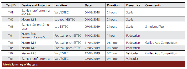
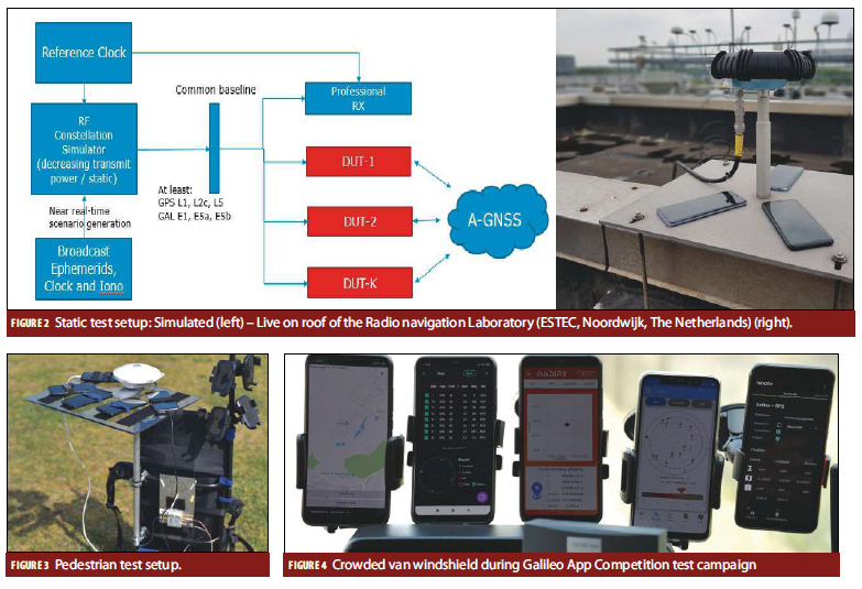
grade antenna installed on the roof of the van, while the smartphone was placed on the van dashboard. The second test was performed on the roof of the ESTEC Navigation Laboratory (Figure 2) with the evaluation kit connected to a geodetic-grade antenna installed on the roof while the smartphone was placed next to the antenna mast, a surveyed reference location.The setup of the simulated static test is shown in Figure 2 (left side). A GNSS RF simulator is used to simulate a near Real-time scenario. The satellite signal power levels are set to values corresponding to open sky conditions in AWGN channel model and then decreased by steps of 2 dB per 600 sec.
Pedestrian tests were run in ESTEC football pitch where for test T.07 words “e”, “ESA” and “GALILEO” were traced with different widths (respectively 19, 15 and 7 meters) to test different position resolutions. A backpack (Figure 3) was equipped with a professional grade antenna, a professional triple-frequency and multi-constellation GNSS receiver, a shelf with Velcro tie wraps host-ing up to 5 smartphones and a power bank. The RTK reference trajectory was post-processed with data from professional receiver and GNOR reference station, installed on the roof of ESTEC Navigation Laboratory. The football pitch is mainly an open sky area, with only a slight building shadowing on its west side. The average walking speed was 3.5 km/h along the pitch perimeter, while in the inner part was as low as 1 km/h, in order to trace the letters on the field with a higher number of points. Kinematic data were also collected in the ESTEC campus with a van for the vehicular scenario. The van equipment included a professional grade antenna, a professional GNSS receiver, a tactical grade IMU system, the chipset evaluation kit and smartphone holders on the windshield to test up to five devices in parallel (Figure 4). Lever arms to the reference antenna were measured by laser scan. The RTK reference trajectory was computed by tightly-coupled integration of GNSS multi-frequency RTK and tactical IMU. The campus presents some obstructions in a few points of the route due to trees and surrounding buildings and the environment can generally be considered mild. Van speed was limited to a maximum of 30 km/h.
Static Test Results: Raw Measurements Accuracy
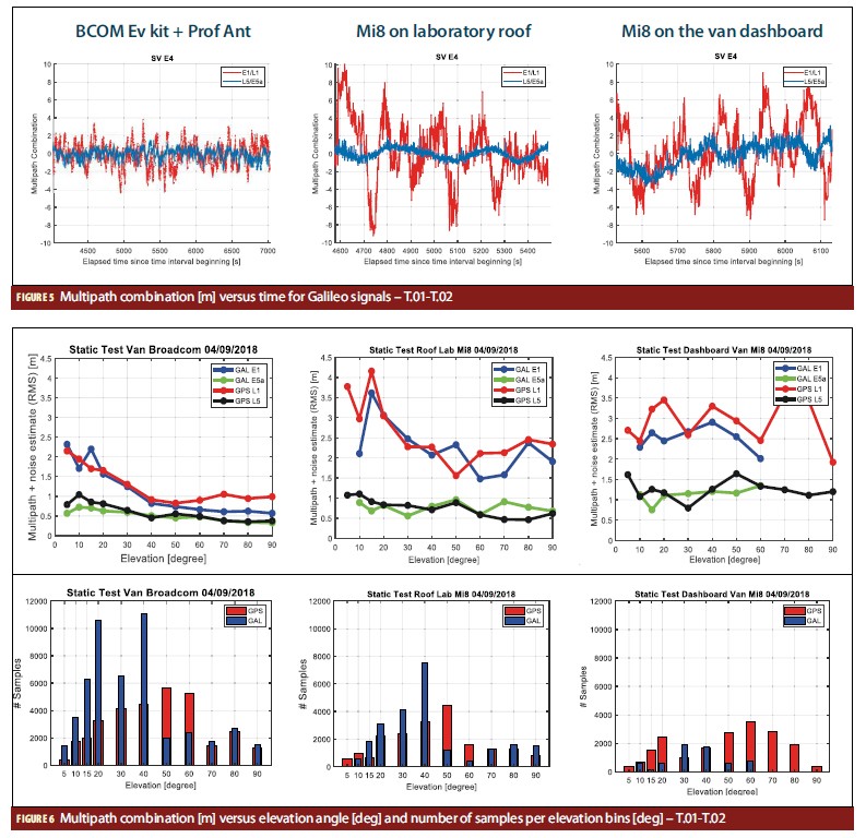
The main contributor to the accuracy of the pseudorange measurements is definitely the multipath error. Figure 5 shows the typical multipath error signatures for a Galileo satellite in a test respectively with the chipset evaluation kit connected to a professional grade antenna installed on the van roof (left), the smartphone on the laboratory roof (middle) and the smartphone on the van dashboard. In the case of the smartphone, such an error can reach peaks of 10 meters amplitude for signals on E1/L1. In the case of Galileo E5a (and GPS L5 as well) the error instead results much smaller and confined between few meters amplitude (max 3 meters in the case shown as example).
The multipath error signatures shown in Figure 5 are computed by using the multipath combination of measurements from the two frequencies. Such combination is a code minus carrier observation where the ionospheric error contribution is removed by the combination of carrier phase measurements from L1 and L5, as described in the following equation:

where  denotes the Multipath on the code phase estimate (in meter),
  denotes the receiver code noise at measurement L1 (in meter), and fL1 and fL2 denote the center-frequency of first and second frequency respectively (in Hz).
N represents the (unknown) ambiguity. During a continuous period of tracking satellite i, N is a constant as long as no cycle slips have occurred. Therefore, the multipath plus noise estimate + is derived from the equation above by subtracting the mean value over a period determined by the epochs of start of tracking, end of tracking, and cycle slips, if any. In order to compute the multipath combination on L1, the first frequency is L1 and the second frequency (noted as L2 in Equation 1) is L5. To compute instead the multipath error on L5, the first frequency is L5 and the second frequency is L1.
The same methodology has been applied to all the satellites visible during the static tests T.01, T.02 and T.03 in order to compute results statistically representative of the multipath errors as function of the satellite elevation angle for different signals (Galileo E1, E5a, GPS L1 and L5) and antenna (professional grade and on the smartphone). The root-mean square errors of the multipath combination is shown in Figure 6.
In the left plot of Figure 6, obtained with the evaluation kit and a professional grade antenna, the effect of the different signal modulations (BPSK(1), BOC(1,1) and BPSK(10)) are visible. There is a slight improvement of the RMS error in the Galileo E1 signal with respect to the simple BPSK(1) of L1CA and notably better performances of GPS L5 and Galileo E5a signals which show RMS errors below 50 centimeters for elevation angles above the 30 degrees. In the other two plots of Figure 5, the performance of the smartphone are shown in two different locations: open sky on the roof of the radio navigation laboratory and on the dashboard of the radio navigation van as example of in-car navigation. In these cases, the variance of the measurements is higher and there is a degradation of performance with respect to the same chipset working with a professional grade antenna, demonstrating the impact of the planar inverted F antenna (PIFA) assumed to be mounted on the smartphone and of a noisier environment (probably due to internal interference in the phone). The improvement of a factor 2 or 3 is still visible in the GPS L5 and Galileo E5a measurements.
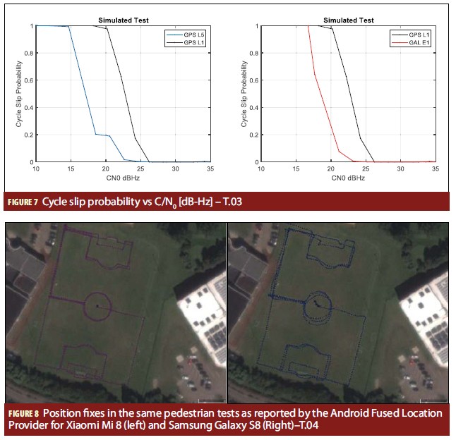
In the case of carrier phase measurements, the multipath combination cannot be used to determine the accuracy. A double difference combination approach has been used, where the difference of carrier phase measurements from two satellites and two different receivers are combined. A zero-baseline test has been performed with the chipset evaluation kit and a GNSS RF simulator used to simulate a “near-real time” static scenario to allow the evaluation kit to download the current ephemeris and acquire signals. Carrier phase measurements from the GNSS RF simulator and the evaluation kit were double differenced for cycle slips detection.
In the case of a zero-baseline test, double differencing allows to cancel errors from the ionosphere, troposphere and satellite clock biases. Since a static test was simulated, the position component of the double differences is constant and can be ignored. Estimating the receiver clock bias and the cancelling it from the double differences, the dominant remaining component will be the phase bias. The phase bias should be constant unless there is a cycle slip. When there is a cycle slip, a jump equal to the size of cycle slip is expected in the double differences.
The probability of cycles slip for GPS L5 is lower than GPS L1 probability. Instead comparing GAL E1 and GPS L1, Galileo E1 has better performance in terms of cycle slip probability.
Pedestrian Test Results: Position Estimation Accuracy
This section presents the results of the pedestrian tests T.06, T.07 and T.08 as described in Table 1. Before showing the results obtained with the MSP3 tool, it is worth presenting the accuracy of the position fixes as reported by the Android Fused Location Provider for the smartphone in comparison to a phone with a simple single frequency multi-GNSS chip of another vendor. The dual frequency measurements along with the GNSS chipset algorithmic enhancements enable a significant reduction of positioning error: as it is clearly visible in Figure 8, the smartphone position fixes (left plot) outperformed the ones produced by the smartphone from another vendor.
Th e results based on the phone outputs are representative of a hybrid position fi x as provided by the GNSS chipset and the additional layer represented by the Android Fused Location Provider. At user level, such a location provider is a kind of black box and its inputs cannot be controlled.
A similar test was performed in April 2019 (T.07) , during the Galileo App Competition. Th is time the GNSS raw measurements as output by the smartphone were using to compute the PVT with diff erent precisions algorithms.
By using different configurations of the MSP3 tool and Google GNSS Analysis tool, we managed to show the results of the accuracy of the horizontal fi xes in the following diff erent confi gurations:
- dual frequency (L1+L5) GPS + Galileo–SPS with raw pseudorange (GNSS Analysis tool)
- single frequency (L1) GPS + Galileo–SPS with raw pseudorange (GNSS Analysis tool)
- dual frequency (L1+L5) GPS + Galileo–SPS with smoothing pseudorange (GNSS Analysis tool)
- single frequency (L1) GPS + Galileo–SPS with smoothing pseudorange (GNSS Analysis tool)
- dual frequency (L1+L5) GPS + Galileo–PPS (MSP3)
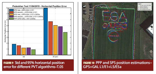
As shown in Figure 9, the results are presented in terms of standard deviation (std) and 95th percentile of the horizontal position error.
It is clear that the dual frequency combination outperforms the single frequency ones. Th e performance in terms of Position Error improves through the usage of smoothed pseudorange, as shown also through the ground track illustration in Figure 10. Th ere are 3 meters of diff erence between single frequency SPS raw pseudorange and dual frequency SPS smoothed pseudorange.
The position accuracy can still be increased using PPP approach. In this case, the standard deviation is below one meter (0.89 meters). Th e carrier phase quality of smartphones measurements is not suffi cient to get to a centimeter level accuracy, as it would be normally expected using a PPP approach with a professional receiver and a professional grade antenna.
Nevertheless, we were still able to trace readable ESA and Galileo virtual words on the ESTEC football pitch, using a dual frequency PPP and dual frequency SPS smoothed pseudorange.
Inertial Sensors for Smartphone Navigation
As mentioned before, smartphones include not only GPS/GNSS chipsets but also mass-market inertial platforms that can be used to perform positioning in indoor and outdoor scenarios. Th is section shows the performance of smartphones and their inertial sensors in terms of gaining information about the user’s current geographical location. Th e Loose coupled INS-GNSS integration approach has been followed, which integrates equations regarding inertial measurements for the positions and attitude estimation. In this integration approach, inner variables, such as accelerometer biases, gyro drift and 3D inertial velocity, are estimated by combining INS information with GNSS measurements (PVT estimations). To retrieve Inertial Sensors and GNSS measure- last generation chips combine GNSS and inertial sensors through a tight integration in a single location hub.
Vehicular Test Results: Position Estimation Accuracy
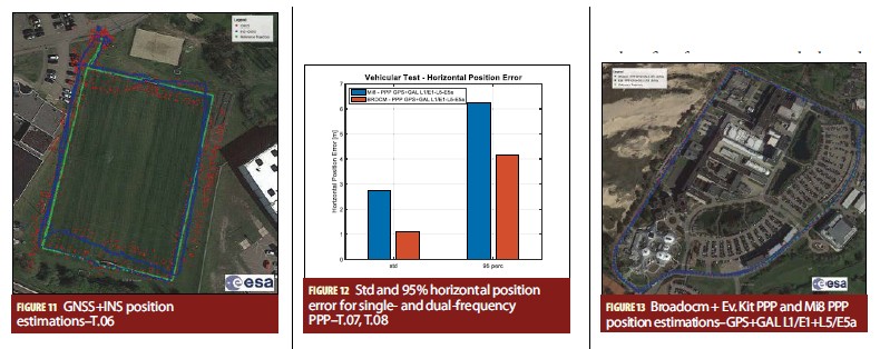
Concerning the kinematic tests, results from test cases T.09 and T.10 (Table 1) are presented below. The tests consist of two different testing sessions, each of half hour driving around the ESTEC campus, with the evaluation kit connected to the professional grade antenna on the van roof (T.10) and the smartphone on the van windshield as in the case of an aftermarket in-car navigator (T.09). The MSP3 tool was used to post processing the data.
By FoM is possible notice the great impact of the antenna type and the antenna position on position error.
A 3.3-meter in 95-perc horizontal error is gained using a professional antenna installed on the van roof.
Conclusions
The first dual frequency mass-market chip commercially available (again, see Manufacturers), has been tested by using the L1/L5 multi-system chipset evaluation kit connected to a professional grade antenna and the smartphone, embedding the same chip but with an internal PIF antenna.
Different PVT solutions have been compared, starting from the fused position fixes provided by the Android Location Provider or directly computed on the basis of the GNSS raw measurements retrieved with the Android GNSS measurements API.
A new Rinex converter able to convert the Android GNSS measurements into Rinex 3.02 format for dual frequency Android phones has been developed and tested during the campaign by using it as input for the MSP3 PVT engine.
Based on the results of the tests performed in static, pedestrian and vehicular scenarios, the following conclusions can be drawn:
- Dual frequency outperforms single frequency positioning, and contribute to a new level of accuracy previously not attainable with smartphones and ultra low cost equipment in general.
- In the standalone smartphone setup, the code noise (multipath) is often the main source of error, hiding the benefits of more accurate clocks and orbital data using PPP algorithms. Also the carrier phase quality of the raw measurements is not sufficient to get to a centimeter level accuracy, as it would be normally expected using professional equipment.
- Wide-band signals in L5-E5 are very beneficial for multipath rejection and contribute to the overall improvement of the positioning accuracy.
- In conclusion, there are still some hardware limitations to overcome, most notably related to the poor quality of the GNSS antenna integrated in smartphones. Nevertheless, the increasing demand for pervasive high accuracy and location-based services may lead to a technology evolution and optimization in a near future.
Manufacturers
The L1/L5 multi-system BCM47755 GNSS chipset has been developed by Broadcom Limited (San Jose, California, USA). A development kit has been provided to ESA in the frame of a cooperation with chipset manufactures to advance the use of Galileo.
For the precise RTK trajectories, the authors used a Trimble (Sunnyvale, California, USA) professional grade antenna with a Septentrio (Leuven, Belgium and Torrance, California, USA) triple-frequency and multi-constellation GNSS receiver. The GNSS RF simulator GNSS9000 is manufactured by Spirent (Crawley, West Sussex, UK).
Nottingham Scientific Ltd/NSL (Nottingham, UK) has implemented the MSP3 PPP tool in the framework of an ESA Technology Research Program contract. The smartphones tested were the Xiaomi Mi8 (Beijing, China) and Samsung S8 (Samsung Town, Seoul).
Acknowledgements
This article reflects solely the authors’ view and does not necessarily represent the official view of the European Space Agency.
We acknowledge Broadcom Limited for the provision of the evaluation kit and the valuable support during the testing campaign and the GSA Market Development Team for their support in the setting-up of the cooperation with the manufacturers. We also acknowledge Nottingham Scientifi c Ltd and Rokubun for the development of the multi-GNSS soft ware processor MSP3 in the frame of the TRP contract “Carrier Phase Positioning Techniques for Mass Market GNSS Receivers”. Th e authors would also like to thank Google for continuous cooperation in the frame of the Galileo App Competition. Special recognition also goes to our ESA colleague Tim Watterton for his very valuable contribution to the development of the GalileoPVT app.
Additional Resources
(1) Crosta, P., P. Zoccarato, R. Lucas, G. De Pasquale, “Dual Frequency Mass-market Chips: Test Results and Ways to Optimize PVT Performance”, Proceedings of ION GNSS+, Miami, Florida, Sept. 2018
(2) Dabove, Ghinamo, Lingua “Inertial sensors for smartphones navigation”, SpringerPlus · December 2015
(3) ESA website, Dual Frequency smartphone app winners prove
https://www.esa.int/Our_Activities/Navigation/Dual-frequency_smartphone_app_winners_prove_power_of_two
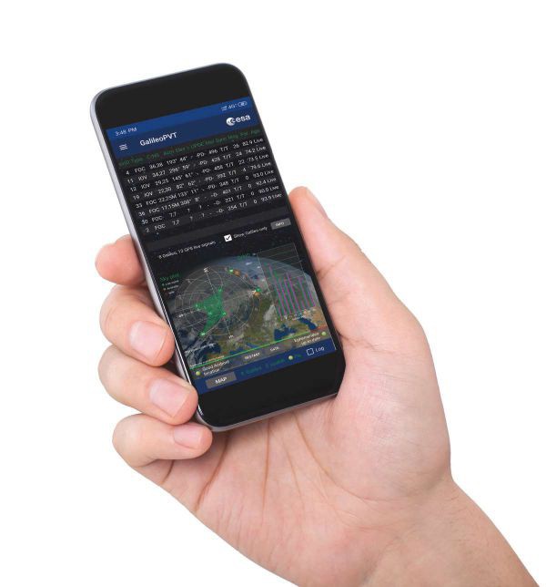
(4) GalileoPVT app, available on Google Play store https://play.google.com/store/apps/details?id=esa.estec.galileo.galileopvt&hl=it
(5) https://github.com/google/gps-measurement-tools/releases/tag/2.0.0.1
(6) https://play.google.com/store/apps/details?id=esa.estec.galileo.galileopvt&hl=en_US
(7) gpsworld.com/positioning-with-android-gnss-observables/
(8) Riley, Stuart, Lentz, Will, Clare, Adam, “On the Path to Precision–Observations with Android GNSS Observables”, Proceedings of the 30th International Technical Meeting of The Satellite Division of the Institute of Navigation (ION GNSS+ 2017), Portland, Oregon, September 2017, pp. 116-129.
(9) Van Diggelen, F., R. Want, W. Wang, “How to achieve 1-meter accuracy in Android”, GPS World, July 3, 2018.
(10) White Paper “Using GNSS Raw measurements on Android devices”available at https://www.gsa.europa.eu/newsroom/news/availablenow-white-paper-using-gnss-raw-measurements-android-devices.
Authors
Paolo Crosta holds a Master’s degree in Telecommunication Engineering from University of Pisa (Italy). He is head of the Commercial User Segment and Navigation System Validation Section at the European Space Agency (ESA), where he provides support to the EGNOS and Galileo programs. He works in the pre-developments of the future RIMS ground stations of the EGNOS v.3 system and, as member of the Galileo Services unit, he supports the Dual Frequency Alliance for Galileo ready mass-market chips and the GSA Task Force on Android GNSS Raw measurements.
Gaetano Galluzzo is the Galileo System Performance Engineer in the Commercial User Segment and Navigation System Validation Section at ESA– European Space Technology and Research Centre (ESTEC) in Noordwijk, The Netherlands. His current responsibilities in the Galileo Project Offi ce include the Galileo system performance verifi cation, development of system monitoring platforms, performance metrics standardization and GNSS receiver test activities.
Rafael Lucas Rodriguez Galileo Services Engineering Manager in the Galileo Project Offi ce at the European Space Agency in Noordwijk, The Netherlands. He has a Telecommunications Engineering Degree from the Polytechnic University of Catalonia at Barcelona, Spain in 1986, and more than 30 years of experience in satellite navigation at the European Space Agency. Managed the fi rst defi nition studies of EGNOS and Galileo and initiated and managed the GNSS Evolutions Programme. Coordinated Initial Service Declaration activities and testing of Galileo mass-market chip-sets, and represents ESA at UN International Committee on GNSS.
Xurxo Otero is a telecommunications engineering graduate from the Technical University of Madrid (UPM). He also holds a MSc in aerospace engineering from TU Delft with a major on positioning techniques using GPS and Galileo. Since 2011 he has been working in diff erent GNSS topics related to EGNOS and Galileo in the International Centre for Theoretical Physics (ICTP-UNESCO) based in Trieste, Italy and in the ESA Technical Directorate based in ESTEC, The Netherlands. He is a radio navigation system engineer at ESTEC, supporting Galileo on test campaigns and receiver technologies.
Paolo Zoccarato holds a Master’s degree in Telecommunication Engineering from University of Padua (Italy) and a Ph.D. in Sciences, Technologies and Measurements for Space from the Centre of Studies and Activities for Space (CISAS) of the University of Padua (Italy). He worked at Curtin University as a PostDoc on PPP-RTK and in Trimble TerraSat GmbH on GNSS network processing for VRS and RTx. He is a Radio Navigation Engineer consultant for the Radio Navigation Systems & Techniques Section of ESA/ESTEC.
Gerarda De Pasquale holds a Master’s Degree in Telecommunication Engineering from Polytechnic of Turin (Italy) with a strong focus on GNSS systems. She worked at u-blox Italia as Junior SW Engineer (Signal Processing). She is now a WP1x System Engineer consultant for the Galileo System Engineering Unit of ESA/ESTEC. She supports the Receiver Test Team in mass-market receiver test campaigns, design and development of software GNSS receiver and PVT tools for harsh environments.
Andrea Melara holds a Master’s degree in Electronic Engineering from University of Messina (Italy) and a Master’s in Nanotechnologies from University of Venice (Italy). Since 2007, he worked in aerospace as RF designer and AIT engineer. He is now a consultant for the Galileo System Engineering Unit of ESA/ESTEC. His activities, as member of the Receiver Test Team, include professional and mass market receiver test campaigns, hybrid precise positioning (RTK and PPP) and customized RFCS scenarios validation.


