
A look at integrity and continuity concepts of a dual navigation architecture developed for civil aircraft during precision approaches.
GABRIEL THYS SAFRAN ELECTRONICS & DEFENSE, AND FÉDÉRATION ENAC ISAE-SUPAERO ONERA, UNIVERSITÉ DE TOULOUSE; CHRISTOPHE MACABIAU, JULIEN LESOUPLE, JÉRÉMY VÉZINET, ANAÏS MARTINEAU FÉDÉRATION ENAC ISAE-SUPAERO ONERA, UNIVERSITÉ DE TOULOUSE; RAPHAEL JARRAUD
The approach phase is one of the most safety-critical segments of a civil aircraft flight. Within the framework of Performance-Based Navigation (PBN), navigation systems must satisfy strict requirements in terms of accuracy, availability, continuity and integrity [1]. These constraints become particularly stringent during the final segment of a precision approach, which extends from the Final Approach Point, approximately 7 nautical miles from the runway threshold, down to the decision altitude [2].
Aircraft guidance during this phase traditionally relies on the Instrument Landing System (ILS) or on Global Navigation Satellite Systems (GNSS) augmented by space-based (SBAS) or ground-based (GBAS) augmentation systems [2]. However, conventional radionavigation infrastructures are progressively being reduced to a Minimum Operational Network intended to mitigate large-scale GNSS outages [3]. As a result, modern precision approaches increasingly depend on augmented GNSS solutions. In practice, the radio-frequency environment around airports may be affected by Radio Frequency Interference (RFI), which can degrade or interrupt GNSS signals. Such disruptions may force aircraft to interrupt the approach and revert to the remaining conventional navigation aids. Ensuring operational continuity, therefore, requires complementary sensors that are passive and robust to RF disturbances.
Optical sensors constitute promising candidates, particularly during the approach phase when the aircraft operates close to the ground and the visual environment provides rich navigation data. Although commercial aircraft are already equipped with onboard cameras to enhance pilot situational awareness during approach, landing and taxiing, these sensors rarely provide operational credit, and their potential remains largely underexploited.
Vision-based navigation relative to the runway has attracted increasing research interest. The European Japanese VISION project developed a hybrid inertial-GNSS-vision navigation system based on an error-state Kalman filter accounting for image processing delays [4]. The C2Land project, led by the Institute of Flight Guidance at Technische Universität Braunschweig, investigates autonomous landing at airports without ground infrastructure by fusing optical and inertial data with non-augmented GNSS [5]. Flight experiments conducted within this project represent some of the most advanced demonstrations of vision-based navigation systems.
Despite these developments, integrating cameras into safety-critical navigation architectures raises important integrity challenges. Vision sensors introduce new failure modes that must be incorporated into the integrity monitoring framework with appropriate risk allocation. However, integrity monitoring methods for vision-based navigation remain relatively limited. Many approaches adapt algorithms originally designed for GNSS, such as RAIM-based techniques using synthetic measurements derived from visual landmarks or batch implementations [6,7] or extensions of AIME using multiple optical sensors [8]. More recent work proposed protection level formulations for hybrid inertial-vision-GNSS systems considering multiple fault modes [9].
However, as highlighted in the survey by [10], the direct application of GNSS integrity methods to vision measurements is generally suboptimal due to the specific characteristics of optical observations and the limited availability of statistical models describing their integrity behavior. This lack of operational experience complicates compliance with the stringent integrity requirements of civil aviation precision approaches as it requires conservative assumptions.
This study builds upon the hybrid inertial-vision-GNSS system introduced by [11], which is designed to ultimately comply with the performance requirements of a PBN CAT I precision approach. It aims to characterize the impact of vision integration on continuity and integrity requirements and to derive false alarm and missed detection probabilities that an integrity monitoring algorithm must verify.
Navigation Dual Navigation System Design
Navigation System Assumptions
The navigation system considered in this article is designed to support PBN CAT I precision approach operations. The system is set in the context of a radio frequency environment potentially disturbed by jamming or spoofing, resulting in potential GNSS service loss of continuity or unavailability. In the PBN framework, any such GNSS event during a precision approach would trigger a navigation system alert, requiring the pilot to initiate a missed approach procedure [1].
The hybrid navigation system integrates measurements from four distinct sensors, including
• A navigation-grade inertial measurement unit (IMU) providing high-quality angular and velocity increments
• A GNSS receiver processing satellite signals (Signal-In-Space) and SBAS corrections to compute a 3D position
• A barometric altimeter used to stabilize the IMU’s vertical channel, supplying altitude information
• A vision system composed of one or more imaging sensors (e.g., monocular, stereo, infrared) and an image processing unit.
The selected vision-based navigation approach relies on landmark-based positioning [12]. The optical sensors observe the aircraft’s environment, referred to as the scene, and specifically detect the runway, from which one or more landmarks are extracted. The 3D positions of these landmarks are supposed to be a priori known and retrieved from the Aeronautical Information Publication (AIP). By associating each landmark with its known coordinates, a line-of-sight vector between the camera and the landmark can be reconstructed. This line-of-sight serves as the vision measurement input to the estimation process. A tightly coupled integration scheme is hence considered in this architecture. The data fusion and state estimation process is based on an error-state Kalman filter [13]. The filter’s structure, along with the mathematical modeling of its propagation and measurement equations, are detailed by [11].
The hybrid navigation system provides guidance system estimates of key navigation parameters, including position, velocity and attitude. It is also designed to provide integrity monitoring and issue alerts in the event of a continuity loss. In parallel, a predefined flight path is derived from a waypoint database and provided to aircraft guidance. This guidance is ultimately used by the flight crew.
Single-Filter Architecture Limitations
A straightforward extension of an SBAS-augmented inertial-GNSS navigation system consists of integrating vision measurements within a triple inertial-GNSS-vision hybrid architecture. Such integration can significantly improve continuity of service because vision measurements can compensate for temporary GNSS outages. In this configuration, a loss of continuity would only occur if both GNSS and vision measurements become unavailable simultaneously. This capability is particularly valuable given the increasing vulnerability of GNSS to RFI.
However, the introduction of vision also brings additional failure modes that must be considered in the integrity risk allocation. When these failure modes are incorporated into the integrity framework, they may inadvertently tighten the integrity requirements associated with the SBAS-augmented GNSS subsystem. Consequently, improving continuity through sensor redundancy does not automatically translate into improved system integrity and may even degrade it if failure dependencies are not properly managed. The limitations of such triple-hybrid architectures are discussed in [14].
The integration of vision into an inertial-GNSS hybrid navigation system introduces a fundamental technical challenge arising from two partially conflicting objectives:
• To increase the continuity of service by leveraging vision measurements to bridge potential GNSS service losses
• To ensure this integration does not increase the integrity requirements allocated to the SBAS-augmented GNSS system.
Technical Solution: Dual Navigation Architecture
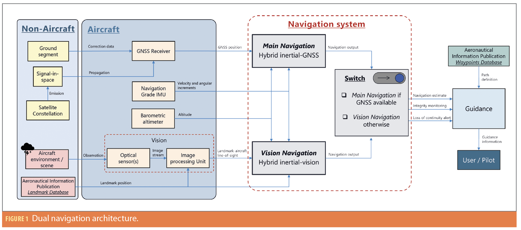
To resolve this trade-off, this work proposes a dual-navigation architecture in which vision measurements are integrated without increasing the integrity constraints imposed on the GNSS subsystem. The core principle of this architecture lies in the implementation of two parallel navigation solutions.
The first, referred to as the Main Navigation, relies solely on measurements from the GNSS, the navigation-grade IMU and the barometric altimeter, deliberately excluding any vision data. As such, this navigation chain corresponds to a state-of-the-art SBAS-augmented inertial-GNSS navigation system.
In contrast, the second solution, referred to as the Vision Navigation, uses only the IMU, barometric altimeter and vision-based measurements, excluding any GNSS inputs. It thus forms a pure inertial-vision navigation system.
During a precision approach conducted by a civil aircraft, the navigation outputs, comprising the estimated navigation states (position, velocity and attitude) as well as the associated integrity monitoring functions and alerts, are provided by either the Main Navigation or the Vision Navigation subsystem. By default, the system delivers navigation outputs from the Main Navigation as long as the SBAS-augmented GNSS service is available. When the GNSS service becomes unavailable and is formally declared out of service, the navigation outputs are transferred to those generated by the Vision Navigation. This transition is handled by a dedicated switching mechanism whose operation is governed by the availability status of the augmented GNSS service.
The use of two parallel navigation solutions, therefore, enable a clear separation of integrity risks associated with GNSS and vision within their respective navigation chains. The resulting dual-navigation configuration is illustrated in Figure 1.
The proposed architecture benefits from the well-established performance of the inertial-GNSS hybrid system as long as GNSS signals are available, thereby maintaining the integrity of a navigation solution that has already been extensively validated. At the same time, it ensures continuity of service in the event of a GNSS outage by incorporating vision-based measurements into the overall navigation process. From the user’s perspective, the system continues to provide the required navigation information without indicating whether it originates from the main or vision-based navigation branch.
Starting Point of the Study
Assumptions and Definitions
Integrity and continuity allocations for the hybrid navigation system are analyzed using fault/risk allocation trees that describe the logical relationships between failure modes and their causes. The interpretation and computation rules of these trees are defined in [2].
Integrity represents the level of trust in the correctness of the navigation information and includes the system’s ability to provide timely alerts [2]. An integrity failure occurs when the Navigation System Error (NSE) exceeds the horizontal or vertical alert limits, producing a Hazardous Misleading Information (HMI) event. This event can be expressed as [17]:

where e denotes navigation error, AL the operational alert limit, y the vector of measurements and Ω the set of measurements considered consistent with the integrity monitor. The integrity risk corresponds to the probability that this event occurs without triggering an alert within the specified time-to-alert [2].
Continuity refers to the system’s ability to perform its function without interruption, assuming it is available at the beginning of the operation. Although a precision approach typically lasts about 150 seconds, the continuity risk defined in [2] only concerns the final 15 seconds of the approach. Continuity loss events include integrity monitor alerts, unscheduled GNSS outages, and RFI disturbances. From a fault detection perspective, these events are primarily driven by detection alarms, which are generally dominated by false alarms. GNSS outages occurring earlier in the approach are instead classified as losses of availability.
Risk Allocation for a SBAS Augmented Inertial-GNSS Navigation System
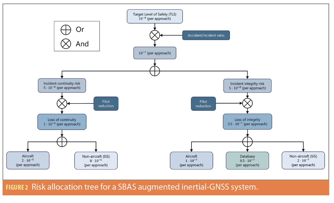
To derive the fault allocation tree for the proposed hybrid navigation system, a reference allocation model is first established based on an SBAS-augmented inertial-GNSS architecture. The resulting structure, illustrated in Figure 2, follows the fault allocation framework developed for SBAS-based APV and CAT I approaches by [15].
The top-level metric is the Target Level of Safety (TLS), defined as the acceptable hull-loss probability per aircraft per flight hour. For approach operations, the TLS is 1×10⁻⁸ per approach, assuming a standardized duration of 150 seconds. Considering one catastrophic accident is associated with approximately 10 incidents, the associated risk budget becomes 1×10⁻⁷, which is equally allocated to continuity and integrity branches.
To derive system-level requirements, an additional breakdown is required. This refinement incorporates the mitigating influence of the flight crew. Operational analyses indicate reduction factors of seven for integrity and 2,000 for continuity, reflecting the fact continuity losses occurring during the final seconds of an approach can often be managed visually, whereas integrity failures may generate misleading guidance.
After applying these factors, the navigation system requirements for PBN CAT I approaches are 1×10⁻⁴ for continuity and 3.5×10⁻⁷ for integrity per approach.
These requirements are allocated between aircraft and non-aircraft subsystems.
• Aircraft subsystems include all onboard navigation components, such as the GNSS receiver hardware, timing modules and processing software. Failures originate from internal causes (hardware faults, power interruptions, interface failures). Compliance with the continuity and integrity requirements is the responsibility of the aircraft manufacturer or avionics supplier, who must demonstrate their equipment satisfies the allocated risk budgets. In certification, continuity compliance is commonly shown using Mean Time Between Failure (MTBF) analysis, whereas the integrity requirement may be validated through design assurance processes and fault detection mechanisms as defined by applicable certification standards.
• Non-Aircraft subsystems correspond to external contributors affecting navigation performance. In an SBAS-augmented architecture, this branch is limited to SIS, including GNSS signals and SBAS corrections. The navigation system must, therefore, ensure compliance with these requirements through appropriate integrity monitoring. Because these non-aircraft requirements relate solely to the external environment, the on-board equipment, specifically the GNSS receiver, are assumed to be ideal (or fault-free), i.e., operating nominally without introducing failures within the measurements. Under this assumption, responsibility for meeting the allocated performance requirements resides with the on-board navigation system, specifically through its integrity monitoring algorithms. Consequently, the non-aircraft continuity and integrity requirements define the performance thresholds the navigation system must meet.
Continuity Requirements for the Vision-Integrated Navigation System
Following the same methodology, the vision subsystem is decomposed into aircraft and non-aircraft branches to clearly delineate responsibility boundaries. This classification enables the identification of risks that fall under the scope of the aircraft manufacturer versus those that must be addressed by the on-board navigation monitoring functions.
Vision Aircraft Loss of Continuity
Aircraft continuity risks originate from failures of onboard hardware or software involved in the vision processing chain. Vision measurements are produced through two main stages: image acquisition by optical sensors and landmark detection using onboard image-processing algorithms.
Failures affecting either stage may interrupt the generation of vision measurements. Optical sensors can be affected by hardware faults such as lens contamination, power interruption or optical degradation, while the processing chain may suffer from processor failures or software crashes. In this study, an aircraft-level continuity loss is defined as any failure of the onboard vision subsystem to produce a runway landmark measurement, assuming the scene observability allows it.
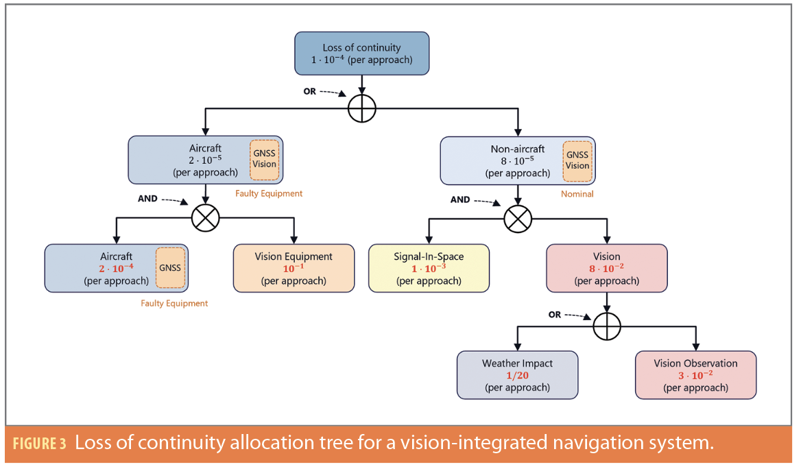
The continuity requirement allocated to the vision function is 10-1 per approach. This relatively relaxed constraint reflects common image degradation mechanisms such as lens contamination or water droplets. Compliance is verified through equipment reliability analysis (e.g., MTBF), and redundancy such as sensor triplication can be used to improve overall continuity performance.
Vision Non-Aircraft Loss of Continuity
Non-aircraft continuity risks correspond to environmental effects that degrade vision measurements while the onboard equipment operates nominally. In this context, the vision subsystem is assumed to produce at least one valid measurement. Under this assumption, continuity loss may occur when the navigation system monitoring declares an alarm, for instance when protection levels exceed the alert limits or when a measurement anomaly cannot be excluded.
For GNSS, environmental disturbances are captured within the SIS concept. In vision-based navigation, the equivalent disturbances arise from the optical environment, which affects the propagation of visible or infrared radiation between the runway and the camera. Environmental perturbations increasing measurement noise are generally referred to as photometric noise, and include poor illumination conditions or strong reflections from the runway surface. These effects increase measurement variance and protection levels, whereas large biases or outliers are addressed within the integrity monitoring framework.
For the hybrid navigation system, the non-aircraft continuity risk is allocated to 8×10⁻⁵ per approach.
Weather Impact
Operational conditions may prevent the vision subsystem from producing any measurement, for instance during night operations with visible-spectrum cameras or under adverse meteorological conditions. Such situations must be explicitly considered in the continuity allocation.
In this study, meteorological conditions preventing vision measurements are classified as non-aircraft continuity risks, as they originate from the external sensing environment rather than from failures of the onboard equipment. This treatment is consistent with the modeling of GNSS outages caused by radio frequency disturbances.
Two modeling strategies can be considered. One approach assumes complete vision unavailability due to environmental conditions is negligible compared to continuity losses caused by monitoring false alarms. However, this assumption is unrealistic because no existing optical system can guarantee a negligible probability of total vision unavailability.
The adopted approach, therefore, explicitly accounts for weather effects by decomposing the vision observation continuity risk into two contributions:
• Losses caused by adverse meteorological conditions, and
• Losses caused by false alarms of the fault detection function.
Assuming one approach out of 20 is affected by weather conditions preventing optical measurements, the resulting continuity risk associated with vision observation is 3×10⁻² per approach. For a fault detection rate of 1 Hz, this corresponds to a false alarm probability of

Continuity Risk Allocation Tree
The introduction of vision into an inertial-GNSS navigation architecture affects both aircraft level equipment continuity risks and non-aircraft continuity risks driven by the external environment. The corresponding allocation tree is illustrated in Figure 3. In this representation, scene observation is explicitly placed within the non-aircraft domain, as it inherently accounts for environmental effects, including meteorological conditions. The aircraft-level vision function is represented by its two main components: the optical sensors and the image-processing unit.
The introduction of vision-based navigation substantially alleviates the continuity requirements previously imposed on the GNSS Signal-in-Space. In both aircraft and non-aircraft contexts, continuity loss occurs only when vision and GNSS are simultaneously unavailable. This architectural change yields multiple benefits. First, it relaxes equipment-level continuity requirements, which is advantageous for both aircraft manufacturers and equipment suppliers. Second, it explicitly addresses the growing risk of radio frequency interference, as the continuity risk allocated to the GNSS SIS is reduced by a factor of 12.5, down to 1×10⁻³ per approach.
Integrity Requirements for Vision-Integrated Navigation
Vision Aircraft Loss of Integrity
Quantifying the integrity associated with airborne vision equipment is challenging. Integrity failures associated with airborne vision equipment occur when erroneous measurements produced by the onboard vision subsystem are accepted as valid by the navigation system and lead to navigation errors exceeding the alert limits. As with continuity risks, compliance with integrity requirements is primarily ensured through equipment certification.
Aircraft-level integrity threats originate from two components of the vision subsystem:
• Optical sensors may experience hardware failures such as calibration errors, lens defects, geometric distortions, or failures of the imaging elements.
• Image processing failures arise from abnormal behavior of the onboard processing chain, including feature detection errors, computing faults, radiation-induced bit errors, or errors in optical multi-sensor fusion. Because the integrity risks considered in the aircraft domain are related to equipment failures rather than external environmental conditions, a core assumption is adopted: In the absence of sensor or processing failures, the produced measurement would be correct.
Failures affecting optical sensors can reasonably be considered random and statistically independent, i.e., not subject to common-mode effects. Under this assumption, and in addition to integrity loss rates guaranteed by the manufacturer through certification processes, these integrity risks can be mitigated through a combination of equipment redundancy, and internal fault detection mechanisms within the processing chain.
These mitigation strategies may reduce the integrity loss probability associated with airborne vision equipment to levels that are either negligible (≈10-9 per approach) or sufficiently small to remain within the aircraft-level integrity allocation already assigned to the inertial-GNSS navigation system (10-7 per approach). Whether a specific allocation should be explicitly assigned to vision equipment remains open to interpretation. Regardless of the chosen allocation strategy, the validation and certification of vision equipment integrity remain the responsibility of the equipment manufacturer, as these failure modes are not monitored by the fault detection mechanisms implemented at the navigation system level.
Vision Aircraft Loss of Integrity
A non-aircraft integrity failure occurs when a vision measurement is corrupted by abnormal errors induced by the external environment. In contrast with continuity analysis, measurement availability is assumed, and environmental effects are considered only through their impact on measurement quality.
The visual environment along the line of sight between the runway and the onboard camera plays a central role. Measurement errors generally consist of two components:
• Photometric noise, representing the nominal stochastic error of the measurement, and
• Deterministic biases, corresponding to abnormal measurement errors.
Photometric noise arises from variations in illumination conditions or scene characteristics, such as overexposure, motion blur, atmospheric disturbances, or runway reflections. Although these effects may increase measurement variance and degrade navigation accuracy, they are treated as nominal realizations within the measurement noise model. The corresponding feared event arises when the photometric noise magnitude becomes abnormally large, corresponding to extreme realizations in the tails of the assumed Gaussian distribution. Although such events may significantly affect navigation accuracy, they are considered as rare normal performance under fault-free conditions, as no underlying abnormal failure or bias is present.
Integrity-threatening events correspond to deterministic biases affecting the estimated line of sight between the landmark and the camera. Two main sources of such biases are identified:
• Incorrect feature detection, where the selected landmark does not belong to the intended runway.
• Incorrect landmark association with the corresponding three-dimensional reference coordinates.
Preliminary studies have proposed models for nominal measurement errors [16] and landmark association failures [12]. However, these results remain limited to specific scenarios and do not yet satisfy the stringent integrity requirements of civil aviation. Consequently, conservative assumptions are typically adopted when modeling vision-based integrity risks.
On-Board Monitoring Assumptions
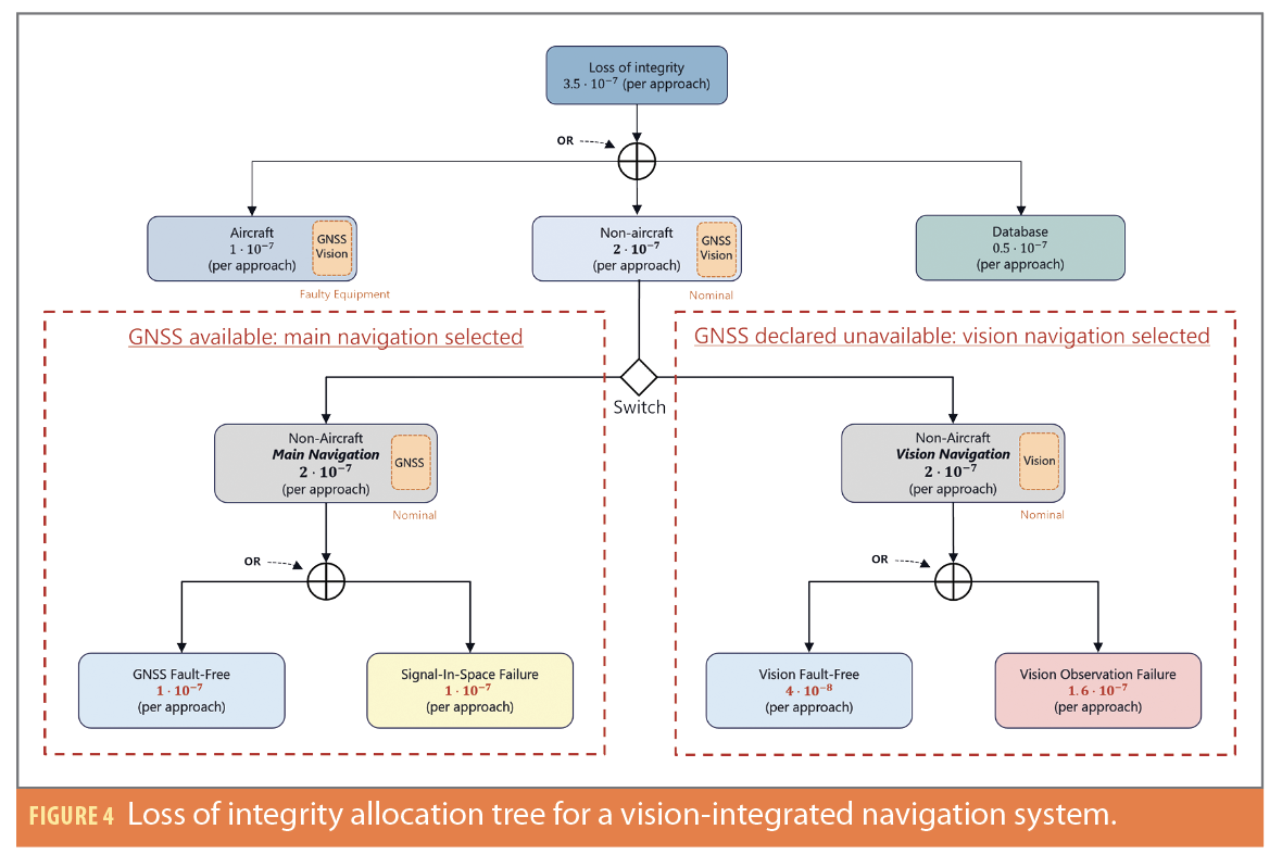
The use of two parallel navigation solutions enables a clear dissociation between integrity risks associated with GNSS and those associated with vision-based navigation. Depending on which navigation branch is active, Main Navigation or Vision Navigation, the set of measurements used to compute the navigation solution differs. As a result, the corresponding failure events, namely GNSS SIS failure and vision observation failure, are mutually exclusive and cannot be jointly considered within a single integrity allocation tree. Each navigation solution is therefore characterized by its own failure modes, its own fault tree, and a dedicated integrity monitoring strategy.
Given that it is not possible to determine with certainty in advance which of the two navigation solutions will be active during a given approach, a conservative assumption is adopted. Accordingly, the full integrity risk associated with the on-board navigation system monitoring, equal to 2×10⁻⁷ per approach, is allocated to each navigation solution without assuming any prior knowledge of the active one.
Main Navigation Integrity Risk Allocation
For the Main Navigation, because it corresponds to a state-of-the-art inertial-GNSS system augmented by SBAS, the sole failure mode to be considered is the SIS failure. The associated integrity monitoring is based on two hypotheses when this navigation branch is active:
H0 Fault-Free: An HMI event may arise due to excessive measurement noise on the pseudo range observations.
H1: Signal-In-Space Failure: One or more satellite measurements are faulty, or the ground segment is corrupted.
The total integrity risk allocated to the navigation system (2×10⁻⁷ per approach) is therefore distributed equally between the two navigation hypotheses of the Main Navigation. The integrity of this navigation configuration is well established in the literature. In particular, the integrity risk allocation tree proposed by [15] can be directly applied, together with standard GNSS integrity monitoring techniques. As a result, the dual-navigation architecture avoids imposing additional integrity constraints on the GNSS SIS performance.
Vision Navigation Integrity Risk Allocation
In the case of Vision Navigation, only one failure mode is considered: Vision Observation Failure mode. When this navigation is active, integrity monitoring is based on two hypotheses:
H0 Fault-Free: An HMI event may result from excessive photometric noise induced by the observed scene.
H1 Vision Observation Failure: A measurement bias affects one or more visual landmarks.
The entire integrity risk of the navigation system (2×10⁻⁷ per approach) is distributed between the fault free and faulty vision hypotheses based on an arbitrary allocation. In this study, the integrity risk associated with the fault-free hypothesis is set to 4×10⁻⁸ per approach, while the risk allocated to the Vision Observation Failure mode is set to 1.6×10⁻⁸ per approach.
Probability of Missed Detection
Based on the proposed allocations, it is possible to derive the missed detection probability required for a fault detection algorithm applied to vision measurements, defined as

Assuming the correlation time of a vision failure and its associated integrity loss extend over the entire approach duration, the required missed detection probability is given by [14]
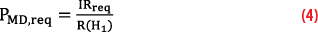
where IRreq denotes the integrity requirement associated with a vision observation failure, and R(H1) represents the occurrence rate of vision observation failures.
This expression highlights that the missed detection probability is inherently linked to the occurrence rate of vision observation failures. However, accurately quantifying this rate remains challenging. Unlike GNSS, vision-based sensors do not benefit from several decades of operational experience and extensive user feedback, particularly in the aeronautical domain. To mitigate this uncertainty, internal consistency checks within the vision processing pipeline, such as image filtering, plausibility tests, or redundancy-based consistency checks, may be implemented to reduce the effective vision failure rate. In addition, the use of external position estimates can constrain the search area for the runway within the image, thereby improving robustness.
A failure probability of 10-4 for vision-based observations has been suggested in [9]. Assuming a correlation time equal to the approach duration, this corresponds to a failure rate of 10-4 per approach. In this study, a slightly more conservative value of 1.6 ×10⁻⁴ per approach is adopted, leading to a maximum allowable missed detection probability of

Dual-Navigation Integrity Risk Tree
The modified integrity allocation tree for the dual-navigation system is shown in Figure 4. The non-aircraft allocation consists of two separate subtrees: one for the Main Navigation and one for the Vision Navigation. The navigation system selects the relevant subtree depending on the active navigation mode. This behavior is represented by a switching element at the top level of the integrity allocation tree. Consequently, the total non-aircraft integrity risk is allocated independently to each navigation branch.
Conclusion
This study investigated the role of vision-based measurements in improving the continuity of navigation services for civil aircraft during precision approach operations. A continuity risk allocation tree was developed to analyze the contribution of vision sensors while distinguishing between aircraft-level equipment failures and observation failures at the navigation system level.
To accommodate the specific characteristics of vision measurements, a dual-navigation architecture was proposed. In this architecture, the navigation system operates with an SBAS-augmented inertial-GNSS solution when GNSS signals are available and transitions to an inertial-vision solution when GNSS is declared unavailable. This design enables the separation of GNSS and vision constraints and leads to the definition of two independent integrity allocation trees corresponding to the two navigation modes.
The proposed framework contributes to the design of resilient navigation architectures capable of maintaining navigation service during GNSS outages. The integrity constraints associated with the vision-based navigation mode were analyzed, and the corresponding false alarm and missed detection probability requirements were derived. These results provide key guidelines for developing dedicated fault detection and integrity monitoring algorithms for vision-based navigation systems intended for safety-critical aviation applications.
Acknowledgements
This article is based on material presented in a technical paper at ION GNSS+ 2025, available at ion.org/publications/order-publications.cfm.
References
(1) ICAO, Performance-Based Navigation (PBN) Manual. Vol. 2. Implementing RNAV and RNP., 2008.
(2) ICAO, Annex 10. Aeronautical Telecommunications. Vol. 1. Radio Navigation Aids., 2023.
(3) FAA, “Provision of Navigation Services for the Next Generation Air Transportation System (NextGen) Transition to Performance-Based Navigation (PBN) (Plan for Establishing a VOR Minimum Operational Network),” 2016.
(4) Y. Watanabe, A. Manecy, A. Hiba, S. Nagai and S. Aoki, “Vision-integrated navigation system for aircraft final approach in case of gnss/sbas or ils failures,” AIAA Scitech 2019 Forum, p. 0113, 2019.
(5) M. E. Kügler, N. C. Mumm, F. Holzapfel, A. Schwithal and M. Angermann, “Vision-augmented automatic landing of a general aviation fly-by-wire,” AIAA Scitech 2019 Forum, p. 1641, 2019.
(6) L. Fu, J. Zhang, R. Li, X. Cao and J. Wang, “Vision-aided raim: A new method for gps integrity monitoring in approach and landing phase,” Sensors, pp. 22854–22873, 2015.
(7) Y. Watanabe, “Vision-integrated navigation and integrity monitoring for aircraft final approach,” IFAC-PapersOnLine, 2020.
(8) C. Tonhäuser, A. Schwithal, S. Wolkow, M. Angermann and P. Hecker, “Integrity concept for image-based automated landing systems,” Proceedings of the ION 2015 Pacific PNT Meeting, pp. 733–747, 2015.
(9) H. Jiang, T. Li, D. Song and C. Shi, “An effective integrity monitoring scheme for gnss/ins/vision integration based on error state ekf model,” IEEE Sensors Journal, pp. 7063–7073, 2022.
(10) C. Zhu, M. Joerger and C. Günther, “Integrity of visual navigation—developments, challenges, and prospects,” NAVIGATION: Journal of the Institute of Navigation, p. 69(2), 2022.
(11) G. Thys, C. Macabiau, J. Lesouple, J. Vézinet, A. Martineau and R. Jarraud, “A high availability inertial-vision data fusion using an es-kf for a civil aircraft during a precision approach in a gnss-challenged environment,” Proceedings of the 2025 International Technical Meeting of The Institute of Navigation, pp. 976-991, 2025.
(12) C. Zhu, M. Joerger and M. Meurer, “Quantifying feature association error in camera-based positioning,” IEEE/ION Position, Location and Navigation Symposium (PLANS), pp. 967–972, 2020.
(13) J. Sola, “Quaternion kinematics for the error-state kalman filter,” arXiv preprint arXiv:1711.02508, 2017.
(14) G. Thys, C. Macabiau, J. Lesouple, J. Vézinet, A. Martineau and R. Jarraud, “Integrity and continuity concepts of a vision-integrated navigation system for a civil aircraft during a precision approach,” in Proceedings of the 38th International Technical Meeting of the Satellite Division of The Institute of Navigation (ION GNSS+ 2025), 2025.
(15) B. Roturier, E. Chartre and J. Ventura-Traveset, “The sbas integrity concept standardised by icao-application to egnos,” NAVIGATION-PARIS, pp. 65–77, 2001.
(16) C. Zhu, C. Steinmets, B. Belabbas and M. Meurer, “Feature error model for integrity of pattern-based visual positioning,” Proceedings of the 32nd International Technical Meeting of the Satellite Division of The Institute of Navigation (ION GNSS+ 2019), p. 2254–2268, 2019.
(17) Blanch, Juan and Walter, Todd 2021, A fault detection and exclusion estimator designed for integrity,” Proceedings of the 34th International Technical Meeting of the Satellite Division of The Institute of Navigation (ION GNSS+ 2021) p. 1672-1686, 2021.
Authors
Gabriel Thys is a Ph.D. candidate at Safran Electronics & Defense in collaboration with ENAC. His research focuses on GNSS, vision-based navigation, inertial systems, multi-sensor fusion, and integrity monitoring algorithms. He obtained a M.Eng. degree in space telecommunications from ENAC . He works as a system engineer in signal processing for high-performance aeronautical navigation systems at Safran Electronics & Defense.
Christophe Macabiau graduated as an electronics engineer in 1992 from the ENAC. Since 1994, he has worked on the application of satellite navigation techniques to civil aviation. He received his Ph.D. in 1997 and has been in charge of the signal processing lab of ENAC since 2000. He is the head of the TELECOM research team of ENAC that includes various research groups.
Raphael Jarraud is a senior expert in inertial navigation and sensor fusions, working for Safran Electronics & Defense. He has 22 years of experience in designing, simulating and testing inertial navigation systems. He graduated from CentraleSupelec in 2003, with a major in control systems.
Julien Lesouple received the Eng. degree in Aeronautics Engineering from ISAE Ensica, Toulouse, France in 2014 and his Ph.D. in Signal Processing from Toulouse Institut National Polytechnique in 2019. Since 2021, he has worked as an Associate Professor at ENAC within the SIGNAV team. His research interests include statistical signal processing, machine learning, estimation and detection theory, filtering, with applications to satellite communications, localization, tracking, navigation, and anomaly detection.
Jérémy Vézinet graduated as an electronics engineer in 2010 and obtained his Ph.D. in 2014 on multi-sensor hybridization from ENAC. He has worked as a Research Associate in the TELECOM Research Team at ENAC since 2014. His interests are GNSS, INS, video-based navigation, multi-sensor hybridization and integrity monitoring.
Anaïs Martineau graduated in 2005 as an electronics engineer from the ENAC. Since 2005, she has worked at the signal processing lab of the ENAC, where she carries out research on integrity monitoring techniques. She received her Ph.D. from the Université de Toulouse. She is the head of Electronics, Electromagnetism and Signal Processing Division and ENAC Engineers and GNSS Master’s Course Director.
 Workshop")


