Snapshot positioning is a technique for determining the position of a Global Navigation Satellite System (GNSS) receiver using only a very brief interval of the received satellite signal, where the sampling time can be more than 100 milliseconds (ms) or even down to as little as 2 ms. In comparison, a conventional GNSS receiver may require anywhere between a few and tens of seconds of signal tracking before it is able to compute its first position.
Since a snapshot receiver can operate with such a short intervals of signal sampling, it is ideally suited for a wide variety of positioning applications where energy use is a significant limitation in adopting conventional GNSS chipset solutions. At the same time, the limited amount of data used requires several changes relative to a conventional GNSS receiver. This article describes the key differences and advantages of a snapshot approach to signal processing and position estimation compared to conventional GNSS techniques.
Snapshot vs. Traditional Receivers
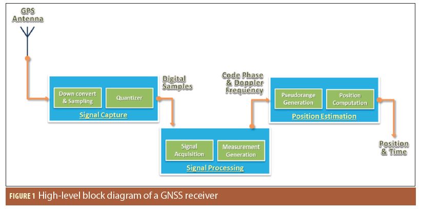
Conceptually, a GNSS receiver can be divided into three logical blocks, as shown in Figure 1:
1. Signal Capture: Collects digital samples of the incoming GNSS Radio Frequency (RF) signals.
2. Signal Processing: Acquires satellites that are detectable and outputs measurements – code phase (pseudorange), Doppler frequency and, optionally, carrier phase.
3. Position Estimation: Computes a position using the code phase and Doppler frequency measurements.
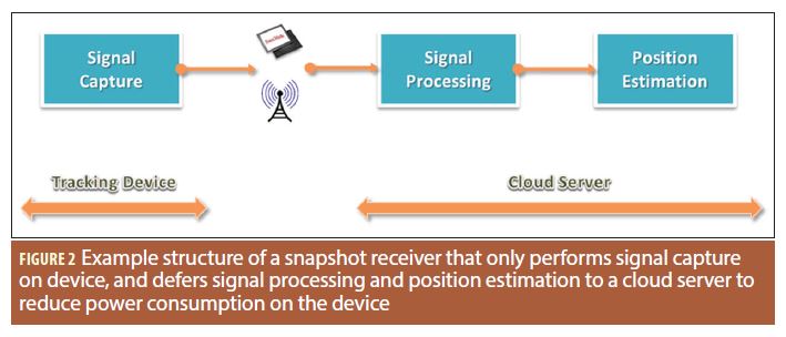
One very unique feature of snapshot receivers is its flexibility to reconfigure and initiate these logical blocks on and off the device being located. For example, since Signal Processing and Position Estimation can be performed long after the signal has been captured, the snapshot receiver can be configured to further reduce power consumption on a battery-operated device by offloading these tasks onto another device such as a cloud-based server, if needed. That being said, with the short sampling time in the snapshot approach, Signal Processing and Position Estimation cannot be performed by conventional means.
The standard steps in Signal Processing to search, acquire, and wait for tracking loops to converge are inapplicable in snapshot positioning. These steps must be replaced with an iterative approach to generate code phase and Doppler frequency measurements (the short sampling times mean that carrier phase data is not available). The Signal Processing block can be computationally complex so the sampling frequency and bit resolution of the digital samples must be carefully chosen for the trade-off between computation time (therefore power consumption) and, sensitivity and measurement quality.
The implications for the Position Estimation arise because there is not enough time to decode navigation data from the received signal. All GNSS receivers require the use of ephemeris information to compute satellite information and, by extension, the receiver position. For conventional receivers, the ephemeris can typically be obtained either directly by decoding the broadcast ephemeris or through alternative means via a communication network; this approach is commonly referred to as Assisted GNSS (AGNSS) technology. In contrast, a state of the art snapshot receiver does not attempt to download/decode the incoming satellite ephemeris information; instead, it takes advantage of utilizing extended ephemeris technology to enable the snapshot receiver to the predict ephemeris autonomously for up to 28 days between ephemeris updates.
Even with the ephemeris obtained by means of broadcast, network assistance, prediction, or post-processing; conventional GNSS processing must still derive the transmit time from the satellite broadcast data. As a result, a pseudorange measurement cannot be obtained without reconstructing the transmit time or using a broader set of techniques also known as Coarse Time Positioning.
Along with the requirement to obtain ephemerides from an alternative source, snapshot receivers cannot estimate receiver position from pseudoranges without an approximate initial time and position of the receiver.
In contrast to snapshot receivers of the past, a state of the art snapshot positioning process described below, has these initial time and receiver position requirements either eliminated or greatly relaxed. Some techniques for coarse time positioning require an a priori time within a few seconds and position within a few km. However, with more recent techniques, the initial position requirement can be relaxed to 75 km, and the initial time to 60 seconds. This wider requirement can be met using Doppler-based positioning so that, ultimately, there is no initial position requirement at all and the initial time requirement is 30 minutes, which can be easily achieved using a Real Time Clock (RTC) that is widely available in most low-cost consumer electronics. Further details are provided below.
Snapshot Position Estimation
As described above, the satellite signal transmit time cannot be decoded in snapshot GNSS receivers. In the example of a conventional GPS receiver, the integer component of transmit time in milliseconds can be derived from the Z-count time of week (TOW) and an integer count of elapsed C/A code epochs. The fractional component of transmit time is the measured code phase.
Then, the pseudorange (ρ) can be calculated as

Where c is the speed of light, tr is the received time of the signal, and tt is the transmit time with an integer millisecond component τt , and the code phase ρ as the fractional component.
Because the integer component of transmit time (τt ) is unknown in a snapshot receiver because TOW cannot be extracted, the full pseudorange must be generated by other means. Broadly, for any coarse time positioning method, the pseudorange is calculated using an estimated range that comes from the initial approximation of receiver time and position, with careful handling of the receiver clock offset.
In particular, using advanced techniques, the transmit time is reconstructed relative to the received time such that pseudorange can be calculated in the standard method of equation 1.
A common representation of pseudorange, ignoring noise and propagation errors, is

where r is the geometric range to the satellite, Δtsv is the satellite clock correction, and b is the sub-millisecond receiver clock bias.
Combining equations 1 and 2, the integer component of the transmit time is solved as

representing the fact that the initial received time in a snapshot receiver may have an error of multiple seconds. This error in absolute time can be considered to be an integer number of milliseconds (ranging code periods) since the fractional component is absorbed by the receiver clock bias. Thus the error in approximated integer transmit time will be identical.

The geometric range r in equation 3 is approximated from the ephemeris and the initial estimates of position and received time. The satellite clock correction Δtsv is known and the code phase p is measured. So all that remains to calculate an approximate integer transmit time is the clock bias b, which is unknown.
An approximate clock bias can be determined by searching for a value that minimizes how far off τt is from an integer value for all satellites. When the best clock bias is found, then all values of τt can be rounded to integers. From these reconstructed transmit times, equation 4 can be used to calculate the pseudorange for each satellite.
It should be noted that, although the error (εt) in the coarse initial received time (tr) can be used in pseudorange construction without inducing pseudorange error, it will still induce an error in the satellite ephemeris calculation. In conventional GNSS processing, fine time is known well enough to be sufficient to be directly applied for position estimation. For any coarse time positioning method, the absolute time error must be an additional estimation state.
The Position Estimation in snapshot positioning can be implemented as an independent least-squares calculation or in a Kalman filter. The solution update interval is customizable for different use cases. In cases where position is only needed at infrequent intervals, accuracy requirements are usually less stringent and a least squares solution is sufficient even with the extra estimated absolute time error. With more frequent updates, a Kalman filter can be used to improve solution accuracy.
Conceptual Structure of a Snapshot Receiver
In a snapshot receiver, each Signal Capture is digitized and saved as a data file. The user has full control over how often and how many milliseconds of digital samples to capture. Signal processing is a key differentiator between the state of the art snapshot receiver and the conventional receiver.
When compared with conventional GNSS receivers, there is a lot of flexibility when designing a snapshot receiver. A conventional receiver usually performs all the blocks of Signal Capture, Signal Processing, and Position Estimation in the hardware device, even if measurements are output for later post-processing. In contrast, a snapshot receiver can be designed to distribute these blocks to optimize energy consumption for their unique hardware platform and, indeed, use cases as described below.
As mentioned earlier, Signal Processing and Position Estimation can be performed long after the signal data has been captured. For use cases where maximizing battery life is more critical than real-time positioning, the snapshot receiver can be configured such that only the Signal Capture circuitry is implemented to temporarily store the digital samples. Signal processing will be postponed until such a time that the digital samples can be transmitted, without affecting the battery life of the device (e.g. during battery recharge), to a remote cloud server for Signal Processing and Position Estimation computations. This is illustrated in Figure 2.
For use cases where a position information is needed at the device, the snapshot receiver can be configured such that the Signal Capture, Signal Processing, Position Estimation blocks are all implemented on a single circuitry, where the extended ephemeris is retrieved from a cloud server at time intervals that has the least impact on the battery life. Such a setup is illustrated in Figure 3.
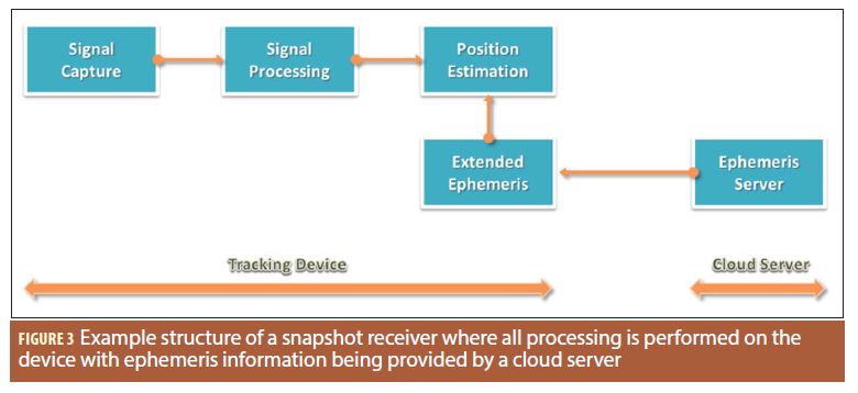
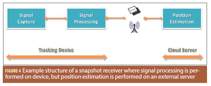
Figure 4 shows a hybrid of the above two use cases, where the snapshot receiver is be configured to capture the digital sample data and then generates measurements prior to transmitting the pre-processed measurements to the remote cloud server for the final Position Estimation computation. In this approach, power consumed for transmitting measurement data is much smaller than for digital samples. Furthermore, the server can estimate a better position solution since it has access to precise orbits.
In general, state of the art snapshot receiver offers system designers a lot of flexibilities to tailor make a low power and low cost GNSS solution that is most suitable for their hardware implementation and use cases. This is fundamentally different from the conventional GNSS chipset that most designers are accustomed to.
In addition to the three configuration modes described above, to minimize energy further, designers can force the snapshot receiver to remain in a “deep sleep” state most of the time. The receiver will only wake up for a few milliseconds to periodically capture a user’s position, store the captured signal and then go back to a “deep sleep” state to conserve power. This essentially creates a GPS-on-demand operating mode.
Internet-connected smartphones have created an “always ON” world that has us conditioned to expect everything to be ON instantly. The penalty for using conventional GNSS receivers to satisfy our “instant everything” desire is the significant energy consumption. In contrast, snapshot receiver technology operates counter-intuitively by forcing the receiver to be always OFF to conserve this precious energy; it uses advanced signal processing techniques that require the receiver to be turned ON just for a few milliseconds. For low-power Wearables and IoT applications where position fixes are needed but energy consumption must be kept to a minimum, a snapshot receiver is ideal.
Additional Resources
For additional information about snapshot based receivers and positioning, please refer to the following resources
[1] “System, Method, and Computer Program for a Low Power and Low Cost GNSS Receiver”, United States Patent US 9,116,234 B2.
[2] Muthuraman, K., (2012) Coarse Time Positioning. Inside GNSS, March/April 2012
[3] van Diggelen, F., (2009) A-GPS: Assisted GPS, GNSS, and SBAS, Artech House, first edition
Authors
Keith Van Dierendonck is a Sr. GNSS Specialist at Baseband Technologies, Inc. in Calgary, Alberta, Canada. Keith has worked in GNSS system development ranging from high-precision to low-cost/low-power for more than 25 years.
Ossama Al-Fanek is a Sr. GNSS Engineer at Baseband Technologies, Inc. in Calgary, Alberta, Canada. Ossama received a PhD degree in Geomatics Engineering at the University of Calgary and has been working on low-power GNSS system development for the past 8 years.
Mark Petovello, co-author, is the editor of this column.


