 FIGURE 1: Proposal to have a single chip GNSS receiver with additional pins to allow for the inclusion of an additional radio
Q: What will limit the spread of multi-frequency GNSS receivers into the mass market?
A: To set the scene, we need to define our terms of reference. By multi-frequency we mean receivers that operate with navigation signals in more than just the standard upper L-band from about 1560–1610 MHz where we find GPS L1, Galileo E1, Compass B1, and GLONASS L1. The obvious additional frequency is the lower L-band, from about 1170 to 1300 MHz, where again the same four constellations have signals.
Future navigations systems, however, have also proposed use of S-band at 2.4 GHz and C-band at 5 GHz. The S-band frequency is the intended slot for the Indian (IRNSS) system.
By mass market, we mean receivers sold to the consumer, in very high volume and with considerable price pressure. The classic case is the mobile phone, now becoming the smart phone and the tablet, for which together the market is hundreds of millions of units per year. However, in a high percentage of these mobile devices, the GNSS function is never switched on; so, the proportion of users who make a critical decision to buy based on GNSS functions is much lower.
The second market is the in-car GNSS system, either in the form of a satnav/PND (personal navigation device) or a real embedded car navigation system — or, more recently, a telematics box buried in the car for e-call or road toll charging. Together these car markets are in the tens of millions of units per year.
The next main question to ask is, WHY? Why would anyone want multi-frequency at all, and why in a mass-market receiver?
The underlying reason, and the primary reason for the dual-frequency design of all the satellite constellations, is to allow for the autonomous measurement and compensation of the ionospheric errors. This is because the errors are inversely proportional to the square of the frequency . . . thus, knowing the frequencies, an iono-free solution can be performed.
The importance of adding this capability to the user equipment itself has been greatly reduced, with iono corrections available through satellite-based augmentation systems such as WAAS and EGNOS and through assistance channels. However, both of the latter correction sources have limited resolution and cannot report iono values for your exact area — they are always an approximation to some degree. Moreover, network-assisted solutions also require a communications channel such as a phone to receive assistance, not always available in remote areas.
So, with a dual-frequency receiver correcting the ionosphere, we have a code accuracy of perhaps five meters being improved to two meters in an open field. The improvement is not enough to justify the effort, but suddenly the code accuracy becomes good enough to resolve ambiguities, allowing carrier-phase solutions, or use of real-time kinematic (RTK) or precise point positioning (PPP) techniques.
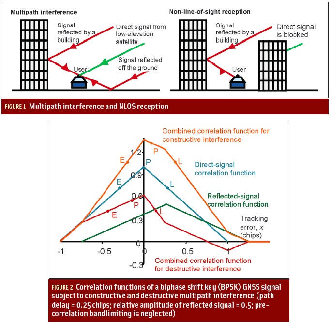
These methods can produce accuracies at the decimeter level, even on a moving platform . . . but, unfortunately, not in the urban canyon, because carrier phase solutions are dependent on PLLs (phase lock loops) and are vulnerable to cycle slips. Moreover, in urban canyons most signals are tracked as reflections.
Nature and Effect of Different Markets
Because people (consumers) who make up the mass market congregate in cities, this limitation on carrier phase solutions is a major negative influence on market take-up of dual-band receivers. In the consumer mass market the main reason for “forward steps” is competition between name brands, trying to gain market share by displaying more or better features than their competitors on the shelf in retail stores (or websites).
Very often these are what we call “tick-box” features (check-box in the United States), meaning while they offer a perceived benefit, the actual benefit is very small. Hence, claiming more channels, or support for WAAS/EGNOS, or multi-constellation capability, all have very little benefit to the mass market because in benign sites (open sky) they are not needed, and indoors or in signal-challenged urban environments where they are needed, they are not up to the task!
I would make an exception with multi-constellation/urban canyon combinations; in a vehicle, these produce excellent results, though still needing some support from other sensors for the pedestrian mode (i.e., the mobile phone).
So, in the true consumer mass market, the driver for multi-frequency is company A wishing to promote a new feature to gain market share over Company B. Against this, neither A nor B can introduce new features until the chip manufacturer offers suitable chips, and this will not happen until a market of many millions of units per year is available, even guaranteed.
The same competition exists among chip suppliers: each feels that if it delivers a feature first, it will gain market share; so, a supplier is pulled in two directions — wanting to be first to market, but waiting for a volume market.
On the other hand, the “light professional” market, where price pressure is much less extreme, actually wants the benefits of multi-frequency, although its volumes are tiny compared with consumer markets. By light professional, I mean agriculture, trains, and so forth — that is, a market not quite needing the accuracy of the surveying receiver, but wanting something better than is available with consumer products.
Consumer Influence
Another critical control over market demand is the level of expertise of the purchaser. In the mobile phone, the purchaser takes almost no interest in the accuracy of the GPS/GNSS function. The manufacturer of the phone also takes very little interest— as long as the accuracy is not so bad that the network operator or other phone retailer rejects the product. This manufacturer is interested solely in cost, and, producing in tens of millions, each extra 10 cents accumulates into some millions of dollars per year.
Embedded in the car, volumes are much lower, but they are still extremely cost-sensitive, largely due to the multiple entities in the sales chain from chip manufacturer to car driver. Again, the typical car driver also has no interest in the accuracy of the car telematics box; it is assumed always to be good enough with little to gain by improving by a meter or two.
An additional consideration is that the time interval between design decisions in the car equipment supplier and the car manufacturer itself, and the eventual delivery of a new car model to the driver, is extremely long — up to four years. The combination of these factors leads to an absence of pressure to upgrade to multi-frequency GNSS.
While the satnav/PND device faces a market that is past its peak, it is still very important. Here the consumer may have some influence, because he is buying specifically for the navigation function, which is not secondary to the smartphone function or the road-holding qualities of the car. However, a customer is usually happy with his GPS-only satnav, as the map-matching function makes it perfectly accurate. With a multi-constellation capability, he is more than happy, as the availability in urban canyons, the final limiting factor, becomes 100 percent.
The only pull for more accuracy in consumer markets is future, more accurate, driver-assistance systems, where the ability to achieve lane detection on the highway could be beneficial, despite the fact that it could never be guaranteed due to local obstruction/reflection issues.
Cost Factors
To recap, then: all the markets would use multi-frequency if it were free. It is, however, not free —because of the requirement for additional silicon and the external passive components, such as antennas and SAW (surface acoustic wave) filters.
These external components themselves may not have any intrinsic extra cost, but the lack of volume means the dual-band version will still be much more expensive than the simple GPS-L1 version. Here’s why: the silicon may be available —again, the intrinsic cost of a few more gates is not the problem; it is the huge development cost of the new chip and the associated software. To make this viable, it must be amortized over many million of units
For the chip manufacturer, the development costs fall into four areas:
(1) the design effort for the RF (radio frequency) front end
(2) the design effort for the digital baseband
(3) the masksets needed for new chips
(4) the software development.
Masksets. In the silicon manufacturing process, the patterns representing the circuits — i.e., the gates, transistors, memory cells, and so on — are printed onto the silicon wafer using a photo-etching process. The masks are the highly accurate transparent slides written by laser and used to project the patterns onto the silicon. More than 30 of them are required for the various layers, and a full set costs some millions of dollars to create.
Existing chip suppliers in the market will be producing new versions every two years or so; so, the maskset cost, which is large, will be incurred anyway. If we can synchronize adding dual-band with such a planned update, the mask costs can be avoided.
The extra silicon area for each chip is not significant for the digital baseband, as silicon feature sizes advance from 65 to 40 to 28 nanometers. The single-chip GNSS receiver consists of a radio, dedicated hardware digital signal processor (DSP), and a processor for measurements and position/velocity/time. The radio converts the signal from nanovolts at gigahertz to just under a volt at baseband frequencies, in steps that amplify, down-convert, and digitize the signal.
Digital Baseband. The digital baseband is the circuitry that must run fast and repetitively, doing the final frequency conversions mathematically, and providing correlation for both acquisition and tracking. Then the processor handles the output. It may itself be divided into a DSP (called the measurement engine) and a positioning engine (doing the real range to lat/long mathematics), or sometimes the positioning engine task may be delegated to the main car or phone application processor.
The DSP and central processing unit (CPU) benefit from shrinking silicon technologies. However, on the radio, silicon area is significant, as inductors and capacitors have circuit values that derive from their physical size, and, so, they cannot be shrunk. Thus, even ignoring development, we cannot load the low-cost product with the extra area.
A Proposed Solution
However, let me describe a solution to solve both the RF design effort and the area problem. For dual band we effectively need two RF front ends, although some clock generation can be shared. We cannot impose the second radio and its expense on all the low-cost users; moreover, the low-cost chip is integrated — radio and DSP and CPU are all on the same piece of silicon.
So, the proposal, shown in Figure 1 (see inset, above right), is to design a low-cost integrated chip with only one radio, but to give it some pins that allow a second radio of the same design to be attached when in use in a dual-band receiver.
This would lead to an RF front end that can be used interchangeably for L1 and L5/E5. Then the low-cost application can use just one, and the less constrained dual-band version needing more accuracy can use two copies of the same RF. This arrangement works well, as the RF chip is often manufactured on its own anyway, either as input to a much bigger processor where integration is inappropriate for noise reasons or as a test chip for a new design.
For the baseband, the extra design effort for the longer faster codes on L5/E5 bands is unavoidable, but this is an investment for the future. Even if the design is not used in volume for a few years, it becomes a library-IP to include in the next chip version at minimal further cost.
As mentioned earlier, the extra logic takes up almost zero silicon area, but more channels may be needed. These are conveniently provided as fully flexible resources that can be used on any frequency, any constellation. Thus, a four-constellation single-band machine may be provided with 48 or 64 channels. Any more is simply for marketing departments to use as a selling point!
Sixty-four channels are still enough for dual band, assuming that most dual-band receivers will use just two constellations when in this mode.
This is because only GPS and Galileo offer the common L1/L5 pair of frequencies, and because dual frequency usually (but not always) implies a carrier phase solution, which is not as straightforward using GLONASS due to its current signals’ FDMA (frequency division multiple access) nature.
The “not always” refers to the point that dual-frequency on a single constellation is still useful for ionosphere correction, even without a carrier phase solution.
If 64 is the base number of channels, vendors will want to out-do each other; so, the number will creep up to over 100. This can also be justified by using excess channels to speed up signal acquisition and cold start.
So, 64 channels allows 16 for GPS L1, 16 for GPS L5, 16 for Galileo E1, 16 for Galileo E5. Even if one wishes to track both pilot and data channels on Galileo and the modernized GPS L1C signals, one could still allocate more than 10 receiver channels per signal component over the three constellations — a requirement not expected until after 2020.
So, as a receiver architect I have shown a route forward for the silicon that can give both RF and baseband solutions on a future update of the chipsets. What is needed now is enough enthusiasm from the system builders in the market to give the silicon vendors the confidence to invest the development resources, both for baseband hardware and for the software.
This should come first from the vendors in the “middle ground” of professional receivers, where market uptake can be rapid, even if not in huge volume. That application segment would be followed by the satnav providers a little later, with the embedded car systems designing-in at the same time, but not reaching production for some years. Only after that could we expect smartphones to incorporate the dual-frequency feature.
Once the software has been developed for the middle-ground receivers, it is easily migrated to the high-volume receivers. Such software already exists in two areas — in the many universities worldwide doing GNSS research and in the professional receiver companies.
However, neither of these is going to drive the market. The university software is largely for software receivers, which are excellent for research but not for low-cost mobiles. So, assuming the software receiver algorithms are divided into the measurement engine doing the digital signal processing and the positioning engine doing the navigation solution, only the positioning engine software would be useful.
For their part, the professional receiver companies wish to keep their knowledge internal as a proprietary asset on which they base their sales. Their receivers also usually employ proprietary application specific integrated circuits (ASICs) or field programmable gate array (FPGA) hardware, rather than running on volume silicon. One route forward would be a cooperation between the silicon vendor and the university, or between the silicon vendor and the professional GNSS company that wishes to move down-market and up-volume.
Additional Resource
Mattos, P. G., and F. Pisoni, “Multi-constellation — to Receive Everything,” Proceedings of ION GNSS 2012, The Institute of Navigation


