Leveraging high-accurate Inter-Satellite Links for communication and ranging among GNSS satellites offers improved and more frequent data dissemination than ground ODTS.
M. LAURENTI, L. MAISONOBE, P. ROLDAN, J. ANTON, P. GUERIN, S. TRILLES, THALES ALENIA SPACE
The accuracy of satellite constellations’ navigation messages continues to increase, with the improved quality of broadcast ephemeris and clocks from satellites directly benefiting positioning accuracy. The next major step toward increased performance leverages Inter-Satellite Links (ISL) [1], which allow both data exchange and navigation measurements (carrier code and phase code). ISL measurements, providing intra- and inter-plane observability that “freezes” the constellation, are considered a pillar for improving broadcast message performance.
Typically, navigation service accuracy highly depends on the ground segment’s reliability, with the satellites’ orbit determination performed using pseudorange and carrier-phase measurements gathered on the ground. The satellites’ ephemerides as well as the on-board clock biases are computed in a ground processing facility and then uploaded to each satellite within the navigation message. This can only occur when the satellite is visible to an uplink facility, posing constraints:
• The navigation message’s update interval is fixed to the revisit period of the satellites given the current distribution of ground uplink stations, putting a burden on the contact plan.
• The performance, in terms of accuracy, of orbit determination and clock synchronization relies on ground-based measures.
• A degraded ground segment (stations failure, massive loss of lock, network break, etc.) would impact the navigation service’s accuracy.
ISLs have been proposed as a solution. A communication link between platforms in orbit allows for inter-satellite data exchange and inter-satellite ranging (ISR). Data exchange means improved and more frequent data dissemination and reduced data age. ISR can serve as an additional observable for the ground Orbit Determination and Time Synchronization (ODTS) process as well as the major input observable to an on-board autonomous navigation algorithm, increasing GNSS robustness.
Based on results from previous studies [1-4], we target accuracies at the level of 10 cm at 95% on the Signal In Space Error (SISE) in this article, including orbit and clock broadcasted within the navigation message projected onto the worst user line of sight when processing both ISL and ground observations. We present the performance level reached with the Navigation Engine for Orbit Determination and tIme Synchronization (NEODIS), which is the core of navigation algorithms developed by Thales Alenia Space for precise orbit determination of satellite constellations. These algorithms allow the real-time estimation of orbits and clocks as well as navigation messages generation with an estimated accuracy in the tens of centimeters.
ISL Technology
According to the International Telecommunications Union (ITU), ISL establishes a radio communication link between orbiting platforms [5]. This link allows the distribution of data, telecommands and telemetry, as well as ranging capabilities. Steerable antennas make it possible to establish an ISL either in plane or out of plane. Different access techniques can be used, according to the specific objectives of such communication and specific design drivers. From the frequency point of view, an ISL can be established both in radio frequency (RF) or optical bands. An optical link, while providing more accurate measures, increases the platform’s complexity. Optical links require a more precise attitude control system, as well as more power and a longer acquisition time. There is no ITU frequency regulation for an optical link. For a RF link, frequency selection should be based on compliance with ITU restrictions and regulations, avoiding interference with other communications links, antenna technology and attitude control specifications, and available power.
The RF link consumes less power than the optical link, has a weaker data rate and is less robust against interference and signal jamming. Some system designs consider using both RF and optical ISLs for ranging and low-bandwidth communications [6]. The transmitted signal can be used as a source of observables to be fed to the ODTS algorithms (either on-board for autonomous navigation or on ground). A PRN code can be modulated on the carrier and then used from the receiving satellite to compute time of arrival, providing a pseudorange measurement. Carrier-phase measurements can be performed by using a frequency locked loop (FLL). In some references, pseudorange measures performed on an ISL are called cross-link ranges.
The main advantages of ISR:
1. A more favorable geometry of measures allows for better observability of cross track and along-track components.
2. Quasi-absence of atmosphere induced delays (constraining the minimum distance of the line-of-sight satellite-to-satellite to the Earth surface).
3. Dual one-way ranges can be computed if measures are shared between couples of satellites.
4. High-quality measurements due to high carrier over noise ratio
C/N0.
ISL Contact Plan
The ISL architecture defines how often measures can be acquired and at which epoch, as well as the possibility of performing full-duplex or half-duplex communication. There are different ways to design the cross-link, different communication schemes and the possibility of installing multiple ISL interfaces per satellite.
Some foresee the implementation of multiple EHF antennas to establish ISL. This improves the system’s robustness in dissemination, monitoring, and control and operability capabilities for services that tolerate ISL latency. It also improves ODTS performance.
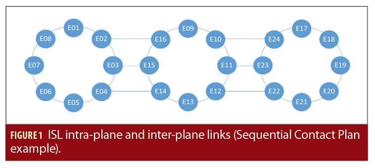
The ISL contact plan envisaged for this experiment are of the point-to-point (“unicast”) type and “sequential,” enabling communication between pairs of satellites, in half-duplex mode either intra-plane or inter-plane (respectively, between satellites on the same orbital plane and on different orbital planes) during repetitive cycles. In a Sequential Contact Plan, a given satellite tries to establish ISL communication to all satellites one after the other. This is done following a fixed matrix, independently of the distance or other parameters that might affect the link itself.
To optimize navigation message performance, the ISL must be established across planes to build one network where all satellites are connected directly or indirectly (Figure 1).
For an exhaustive contact plan definition, the time slot, pointing delay and communication cycle must be defined:
Time slot: The duration of a communication interval between two satellites, which includes two sub-slots of equal duration. During the first sub-slot, Satellite A transmits to Satellite B and vice versa during the second sub-slot. The transmitted signal is used by the receiving satellite to make measurements and receive data.
Pointing delay: The delay between one time slot and the next, necessary to point the antenna toward the next satellite. It also includes other additional delays due to the acknowledgment messages necessary to begin transmission.
Communication cycle: The time needed to communicate with all the constellation’s satellites. At the end of a single communication cycle, all possible couples of satellites have established an ISL and exchanged data/ranging.
ISL One-Way Ranging
ISL can be used to perform conventional ranging measurements between satellites. The measurement used is a propagation time measurement calculated by correlation on a pseudo-random code modulated and sent by a transmitter. The satellite knows the position of each transmitter in the terrestrial coordinate system. The signal is sent continuously, and the satellite can perform its measurements using CDMA modulation on the received signal. From the moment the transmitter is in
visibility, each ∆tmeas in the time scale specific to the satellite, a new measurement is carried out.
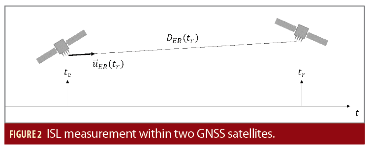
Considering all known effects, the model for this carrier-code measurement between emitter E and receiver R antennas center of masses is:

• The time (tr,te) expressed in GNSS system time reference (STR) and the apparent proper time at emitter teEand receiver trR are tied by the following relationship:

• δt is the apparent satellite clock bias (containing hardware bias) with respect to STR, that can be approximated by a quadratic polynomial

• DRE is the geometric distance between emitter and receiver center of mass (COM) equal to

with and
are the position of receiver and emitter COM respectively, and τRE being the transition time, τRE=c(tr-te);
• ∆trel is the eccentric relativistic effect affecting both receiver and emitter satellites
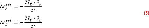
with and
the velocity of receiver and emitter COM respectively;
• is the Shapiro effect, being the effect on the signal propagation due to Earth gravitational field;

Where μEarth=GMEarth,rR is satellite R distance from the center of the gravity field, rE the distance of satellite E and r0 the distance of the line of sight from satellite R to satellite E from the center of the Earth gravity field.
• BR and BE are the instrumental delays (in meter) relative to the ISL antenna on the receiving chain for R and the transmitting chain for E.
• PCO is the phase center offset relating to the emitter and receiver satellites. It represents the distance between the satellite’s center of mass and the apparent source of radiation (center of phase) on the ISL antenna. It is different from L-band antennas used for transmitting the signal in space and is assumed to be known as a function of the ISL pointing.
• εM is the measurement noise.
Because ISR measurements are rejected when the geometric link is closer than 1,000 kilometers to Earth, there is no ionosphere effect, so the model does not take ionosphere delay into account.
The measurement noise is modeled as a Gaussian error and depends mainly on the length of a PRN chip. In general, the error is approximately equal to 1% of this length. It can be computed as:

fCH is the PRN modulation frequency (fCH=10.23 MHz classically). However, it is mainly related to delay locked loop (DLL) performance.
The previous formulations of the measurement equations do not explicitly show satellite velocities. That only comes from the state transition matrix, which may be insufficient for its estimation. The problem is even more noticeable if we consider the low observability of speed during the limited duration of the measurement arcs. For these reasons, one way ranging measurements will be coupled with conventional Doppler measurements that provide specific information on satellite velocity and improve its observability. The model for this measurement derives directly from the Doppler effect definition:

The variation of the reception frequency fr with respect to the transmission frequency fe is proportional to the relative radial velocity between the two satellites

Where is the unitary vector of the line of sight which is computed at the epoch tr of the measurement:

More specifically, for a transmitted signal at frequency fE, it is true for the received frequency fR

Where is the pseudorange rate, the time derivative of Equation 1 , and ∆f=fR–fE is the output of the PLL. Equation 12 is the link between the observable Doppler shift and the state of the satellite and clock:

Neglecting the time variation of the instrumental delays, the PCO and assuming the time derivative of the Shapiro effect is small in comparison to the measure and noise themselves, the first term in Equation 13 can be expressed as:

Where the r apex means it is the projection of the velocity on the line of sight between the two satellites. Including this measure introduces two additional estimation variables
() and (
) even if it is possible to use the transmitting satellite clock’s drift contained in the navigation message for the measurement modeling computation.
The propagation time is computed iteratively from the positions of the satellites at the time of the measurement.
ISL Dual One-Way Ranging
ISL increases the robustness of the GNSS constellation to temporary loss of contact with the ground segment. In this degraded scenario, the space segment could still rely on ISL based observations to perform its own OD and maintain the generation and provision of a navigation message. These measurements are the combination of an orbit-dependent part and a clock-dependent part, which includes both receiver and transmitter clock biases. ISL observations are gathered one at a time at specific epochs. The most used solution for autonomous navigation [2, 8] separates the orbit determination problem from the clock synchronization problem. The construction of the dual one-way ranging measurement at epoch t0 between satellites A and B makes this possible. We describe a solution based on dual one-way ranging.
At epoch t1 in the proper time of satellite A, satellite A performs with the satellite B a pseudo-range measurement ρAB (t1). During the next sub-slot, satellite B measures the pseudo-range ρBA (t2) with the satellite A at epoch t2 of its proper time. These measurements, which correspond to different epochs, are shared (each satellite measures the forward ranging ρ: AB and receives the backward ranging ρ: BA) and can be written as:

Where takes into account all effects due to relativity, instrumental bias, antenna offset and εm is the measurement noise.
To combine the measurements provided by satellite A and B, it is necessary to calculate corrections dρ to bring them back to the same common epoch, t0, expressed in system time. In general, these corrections can be expressed nominally as:

Where represents the theoretical pseudorange computed using prior orbital and clock information. The accuracy of such correction depends on the accuracy of a priori knowledge of the receiver and transmitter states at system epochs t0, t1 and t2. There are multiple ways to recover the satellite states and clocks at the common epoch t0: dynamical propagation if both receiver and transmitter state vectors are available, analytical models and linear approximations.
A linear approximation is valid as long as the time difference t2–t1 is small enough to stay under the assumptions of the linear approximation. The linear corrections are a function of the speed of the satellites and the drift of the clocks. Each correction is calculated:

with and
. Velocity
and
are taken respectively at the times t1 and t1–τAB.
The unitary vector of the line of sight is computed at the epoch t1 of the measurement:

Using the satellite link in the other sense it is easy to compute the correction dρBA

with

The accuracy of this correction is directly related to the time interval between the two pseudorange measurements t2–t1, the accuracy of satellite velocity and clock drift (which are deduced from the global navigation filter). Once the corrections have been calculated, we can construct the two-way measurement at the common epoch by adding the corrections dρ:
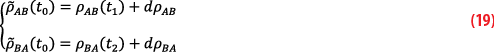
This leads to the following formulation:
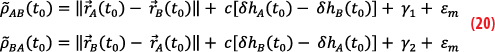
Equations 19 and 20 deal with the same geometric distance at the common epoch and the same clock biases. This allows separating the clock from the orbit problems by calculating dual one-way ranging:
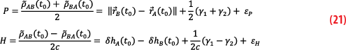
In these formulas, instrumental delays included in the terms γ1, γ2 can be assumed to be sufficiently steady, so no significant changes occur between t0, t1 and t2. All relativity delays (accounting for the relativistic clock corrections on both receiver and transmitter and the Shapiro effect) also can be considered invariant over the time steps. The measurements P and H can then be used in two independent filters: a filter for orbit determination and another filter for clock synchronization.
Dual one-way ranging corresponds to the state of the art, but to actually exploit this solution, the communication protocol used for the ISL should respect two major constraints:
• In a half-duplex communication scheme, an additional sub-slot must be included at the end of every given time slot, during which forward ranging is shared. This means A talks to B then B talks to A, then again A talks to B. This way, it is possible for any satellite to gather both forward and backward ranging observations, necessary to build P and H.
• If linear approximations are exploited, sub-slot durations should be as short as possible. The accuracy of the linear correction dρ applied to bring the observables to a common epoch depends directly on the time elapsed between the forward and the backward ranging t2 – t1. If this time is too large (even larger than a few seconds), the linear approximation used to compute dρ is not valid anymore and additional errors are introduced in the observations.
ODTS with ISL and Ground GNSS Measurements
The main challenge of ISL measurements is inserting them into the global ground GNSS measurement because they are not synchronous. Usually, ground GNSS stations process the ranging measurements at a given frequency (given by the filter step) while ISL measurements are timestamped at any moment between two consecutive steps, according to the specific contact plan and ISL definition. Therefore, clock biases coming from ISL measurements cannot be introduced; they are in the ODTS filter because they do not represent the clock synchronization bias at the same epoch.
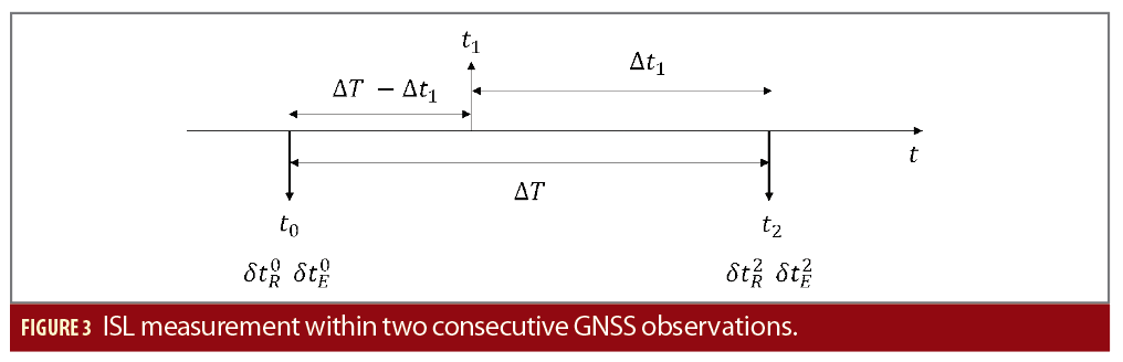
Assuming satellite R has measured at epoch t1 the cross-pseudorange ρRE (t1) with satellite E, which can be computed through Equation 1, two additional clock biases should be added to the state vector for each ISR measurement. So, one equation adds two unknowns to the problem. To reduce them, clock biases δtR (tr) and δtE (te) must be computed using the closest snapshot resolutions. Assuming the time dynamic of the satellite’s clock evolves linearly on short intervals (a few minutes), the satellite’s clock bias at time t1 can be expressed as the satellite’s clock offset at system epochs t0 and t2. A classic method consists in applying a linear interpolation to compute the clock offset information at time t1 using the clock offset information at time t0 and t2, as depicted in Figure 3.
More precisely, given and
at system epochs t0 and t2 corresponding to two consecutive filter steps (t2–t0=∆T), we can express
as (the same procedure applies to Satellite E):

Where f(t) depends on the specific interpolation method selected (this can be extended to include more interpolation points). In practice, the interpolation intervals are very small because the ODTS filter step ∆T is usually fixed between 30s to 180s to remove time correlations between measurements.
Performance
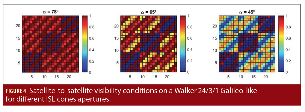
The performance assessment is done on a synthetic scenario that introduces ISL measurements. For ground ODTS, a network of 14 ground stations is considered. The reference constellation is a Walker 24/3/1 with a semi-major axis equal to 29,600 km (Galileo-like constellation, 24 satellites distributed uniformly on three orbital planes with RAAN spacing of 120°). The matrices show the satellite-to-satellite visibility conditions over a two-day period. The minimum elevation angle within the ISL reference frame is varied from 12° (α=78° is the visibility cone semi-aperture) and 45° (α=45°). The minimum elevation angle in the ISL reference frame was fixed to 12°, corresponding to the first plot on the left of Figure 4 (the same type of visibility matrix for different geometries is proposed by [7]).
The color map shows how long a few given satellites are in visibility of each other. Satellites on the same plane are always in visibility of each other, excluding one satellite eclipsed by Earth on the opposite side of the orbital plane. Satellites on different planes have very good visibility conditions >80% of the time.
Ground Measurements and Inter-Satellite Ranging
Ground one-way ranging is processed with ISL one-way ranging in the ODTS filter. The first plot in Figure 4 shows that with α=78°, all satellites on other planes are in visibility >80% of the time while satellites on the same plane (excluding satellites with a true anomaly spacing of 180°) are in constant visibility.
In this simulated scenario, the satellite clock is modeled as a Passive Hydrogen Maser (PHM) clock. The achievable measurements error depends on DLL and ranging signal properties:
• Modulation scheme of the ranging signal
• Early-late spacing (to perform the alignment between the replica and received signal)
• Signal power to noise ratio C/N0
• Pre-integration time
The expected and simulated performances of ISL based measurements are:
• RMS < 0.05 m for satellite-to-satellite one-way ranging code observation error (1 sigma) for any link established
• RMS < 0.00095 m/s for satellite-to-satellite one-way Doppler observation error (1 sigma) for any link established
The ODTS filter processes both Code and Doppler observables.
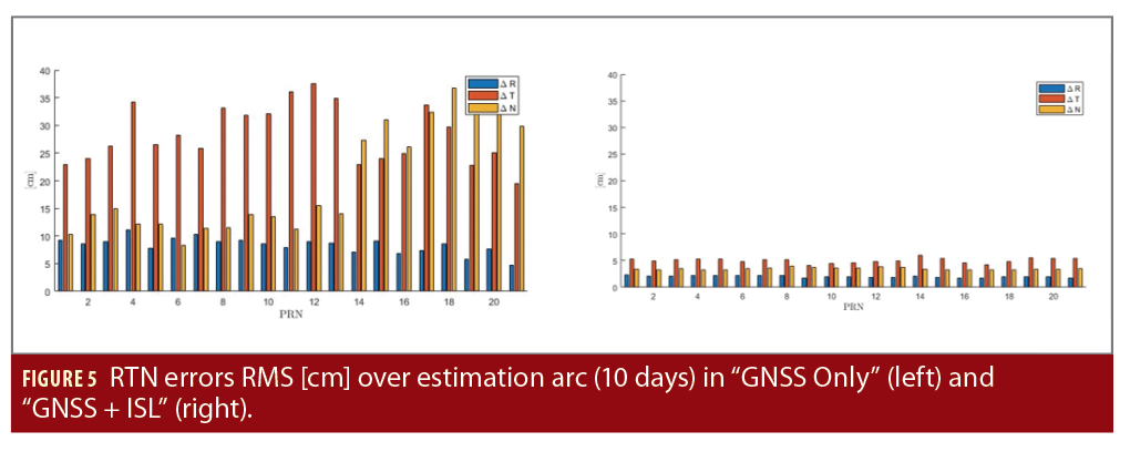
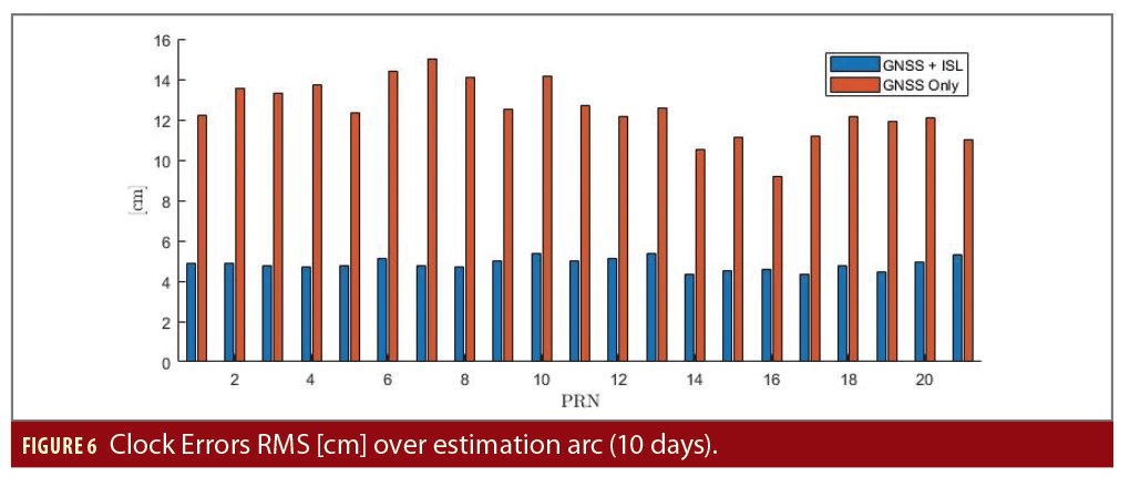
We assessed performance in two ways: Comparing the estimated orbit and clock to the reference data, truth orbit and clocks, and the improvement on the SISE of the broadcast navigation message at 20 and 100 minutes, respectively. Estimation errors are projected in the Local Orbital Frame (x, or radial, is aligned with the satellite position vector; z, or normal, is parallel to the orbital angular momentum and y, the tangential direction, completes the triad). In this specific reference frame, it is easier to evaluate the improvement of the problem geometry due to the ISL observables and their impact over the errors on the user-satellite line of sight. Figures 5 and 6 show the errors during estimation (after convergence) on a scenario with and without ISL observables. The errors are computed over 10 days on all satellites. The orbit RMS values are presented in Figure 5. Clock synchronization errors are shown in Figure 6.
Figures 5 and 6 show ISL observables drastically improve the observability of all main directions, both in-plane and out-of-plane components. The ISL lines of sight make the geometry significantly more favorable. The clock errors are reduced because the filter can more easily separate orbital errors along the radial direction from the clock bias errors. The RMS on the 3D positioning errors during estimation is below 7 cm when including ISL ranging and Doppler within the filter (with all hypotheses made over the ISL noise).
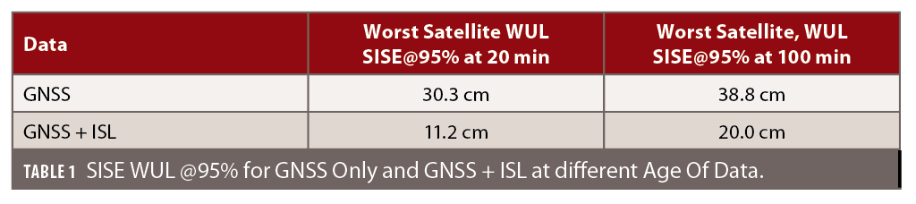
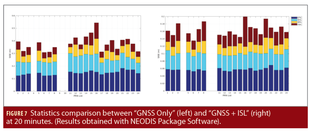
The next results refer to navigation message errors with both propagation and compression errors included. Compressing the ephemeris into reduced navigation message parameters introduces additional errors. The navigation message is always computed on a propagated ephemeris. The clock bias is extrapolated using the well-known 2nd order polynomial. The 95th percentile of SISE for the Worst User Location (WUL) is assessed for the worst satellite after NEODIS convergence (48 hours for GNSS only and 24 hours for GNSS + ISL), using the generated navigation messages, at 20 and 100 minutes, respectively (Table 1). The WUL is defined as a user located on the edge of a 5° elevation visibility cone.
Figure 7 compares the results of two experiments: GNSS measurements only and GNSS measurements + ISL measurements, both nominal scenarios, without feared events (details and statistics per satellite are provided, 95% values are shown in light blue).
On-Board ODTS with Inter-Satellite Ranging Only
Whenever contact with ground is lost, the GNSS constellation can continue performing its own ODTS exploiting only ISL observations. If we assume no link with the ground segment can be established, there are two main approaches to an on-board autonomous navigation filter exploiting ISL only:
1. Distributed: Each satellite performs its own ODTS using ranging to other satellites, navigation messages containing the last received clock and orbit estimates for all other satellites and their associated covariance.
2. Centralized: Ranges and state vectors are shared and centralized in one constellation ODTS filter that estimates all satellites’ clocks and orbits at the same time.
The broadcast navigation message shall be computed with respect to a common timescale and allow users to compute satellite positions in a Terrestrial Reference Frame. This is why two main issues shall be accounted for: how to build a common timescale and how to accurately extrapolate the Earth orientation parameters and perform the rotation from the inertial to the Terrestrial Reference Frame.
Time Synchronization
In the absence of a common master clock, the time synchronization problem cannot be closed by imposing a single reference physical clock. Usually, satellite clocks are estimated with respect to a chosen master clock on the ground.
Different alternatives are possible:
1. Satellite master clock: A given satellite takes the master clock role. Clock biases are computed with respect to this specific SV. The performance is limited by the clock’s stability and has the major drawback of having a single point of failure.
2. Composite clock: A common timescale is built using all or a selected sub-set of SV clocks.
A solution based on a composite clock is expected to provide better long-term stability and also be more robust to any individual satellite feared event. During autonomous navigation, synchronization to external timescales cannot be accomplished. Constraints of relative difference between the constellation reference time and UTC cannot be directly controlled if no ground contact is present.
Earth Orientation Parameters
When contact with the ground segment is lost and only inter-satellite measurements are available, Earth orientation parameters become unobservable and cannot be estimated by the filter. The consequence is minor with respect to the constellation dynamics because orbits are propagated in an inertial frame. Some force models depend on Earth fixed frame (due to the gravity field), but a mis-orientation of a few meters does not significantly change the gravity field. The computation made on-board remains very accurate even in the presence of small orientation errors. The lack of Earth orientation parameters update has a critical impact on navigation message generation because it is tightly bound to the Earth fixed frame. It is therefore mandatory for the constellation to have a prediction model on board that can be applied until contact with ground is recovered. Accurate long-term models can be computed on historical data. This model can be easily uploaded to the space segment during nominal operations and used when autonomous mode is triggered.
Conclusions
Simulations including ISL measurements within the NEODIS software package demonstrate ISL-based observables have a significant impact on orbit performance and satellite clock estimation, and therefore on user positioning performance via the navigation message. In the ground based ODTS, we have shown ISL based observables allow improvement up to three times on the SISE orbit and clock with respect to an ODTS based on ground observations only, achieving 11 cm 95% SISE orbit and clock at 20 minutes. This technology could make autonomous on-board navigation possible during a long-lasting loss of contact between the constellation and ground stations.
References
(1) Fernandez, F. A. (2011), “Inter-Satellite Ranging and Inter-Satellite Communication Links for enhancing GNSS Satellite Broadcast Navigation Data”, Advances in Space Research Volume 47, Issue 5, 1 March 2011, Pages 786-801
(2) Lv, Y. et al. (2020), “Evaluation of BDS-3 Orbit Determination Strategies Using Ground-Tracking and Inter-Satellite Link Observation’, Remote Sensing, 2020, 12
(3) Wolf, R. (2000), “Satellite Orbit and ephemeris Determination using Inter-Satellite Links”, Dissertation, 2000
(4) Eissfeller, B. et al. (2000), “Autonomous Satellite State Determination by Use of Two-Directional Links”, International Journal of Satellite Communications 18 (2000): 325-346
(5) ITU Radio Regulations, Section IV. Radio Stations and Systems – Article 1.22, definition: inter-satellite service / inter-satellite radiocommunication service
(6) https://www.esa.int/Enabling_Support/Space_Engineering_Technology/Shaping_the_Future/Optical_inter-satellite_links_are_best_tech_for_Galileo
(7) Kur, T. et al. (2021).F “The Application of Inter-Satellite Links connectivity schemes in various satellite navigation systems for orbit and clock corrections determination: simulation study”, Acta Geodaetica et Geophysica volume 56, pages 1–28 (2021)
(8) Yang, Y. et al. (2019). “Inter-Satellite Link Enhanced Orbit Determination for BeiDou-3”, 2019 Journal of Navigation 73: 1-16
Authors
Marco Laurenti is a Navigation Engineer at Thales Alenia Space. He holds a master’s degree in Space and Astronautical Engineering from La Sapienza University of Rome, Italy and an advanced master’s degree in Space Systems Engineering from the Institut Supérieur de l’Aéronautique et de l’Espace in Toulouse, France. Since 2019, his areas of activity are LEO Precise Orbit Determination and GNSS Orbit Determination and Time Synchronization algorithms.
Luc Maisonobe is an expert in astrodynamics with more than 35 years of experience in all space fields, from studies to mission analysis and operations, and from Earth observation to navigation and telecommunication. He is the creator and main developer of the Orekit open-source space flight dynamics library. Since 2022, he belongs to the orbitography team in the Navigation Domain at Thales Alenia Space.
Pedro José Roldan Gomez is a specialist in time and frequency systems at Thales Alenia Space. He holds a Ph.D in Climatology and two master’s degrees in Aerospace Engineering and in Meteorology and Geophysics from the University of Madrid, Spain. His areas of activity include GNSS orbit determination and time synchronization algorithms, applications of GNSS for precise positioning and timing, and algorithms for time transfer, generation and steering of timescales.
Julie Anton is a specialist in orbitography algorithms at Thales Alenia Space. She holds a master’s degree in Space and Aeronautical Engineering from ISAE-Supaéro. Her areas of activities include LEO Precise Orbit Determination, GNSS Orbit Determination and Time Synchronization algorithms and Galileo system performance analysis.
Pierre Guerin is an expert in orbitography algorithms at Thales Alenia Space. He holds a master’s degree in Astrophysics and Space Technology from the Paul Sabatier University of Toulouse, France. Since 2014, he has contributed to various space flight dynamics systems, his main field being LEO Precise Orbit Determination and GNSS Orbit Determination and Time Synchronization algorithms.
Sébastien Trilles is expert in orbitography and integrity algorithms at Thales Alenia Space in Toulouse, France. He holds a Ph.D. in Pure Mathematics from the Paul Sabatier University and an advanced master degree in Space Technology from ISAE-Supaero. He heads the Performance and Processing Department where high precise algorithms are designed including orbit determination, clock synchronization, time transfer, reference time generation, integrity and ionosphere modeling algorithms for GNSS systems and augmentation.