
A new GNSS antenna array algorithm helps simultaneously estimate the antenna array attitude and direction of the incoming multipath wave fronts, improving attitude and position accuracy.
DANIEL S. MAIER, MATHIAS PHILIPS-BLUM, THOMAS PANY, UNIVERSITÄT DER BUNDESWEHR MÜNCHEN
EMANUELA FALLETTI, LINKS
PAOLO ZOCCARATO, FRANCESCA ZANIER, ESA/ESTEC
In the field of positioning and navigation, there are applications that are expected to gain more and more market share in the coming years. Two of them are autonomous vehicles (AV) and augmented reality (AR). Both are expected to go from a niche exploitation today to a widespread inclusion in mass-market devices tomorrow. Such applications demand high precision in positioning and attitude in adverse environments on the one hand, but also have clear limitations in the cost of the equipment, which must be produced in large scale in the case of automotive components and be affordable in the case of AR devices. For example, extensive tracking technology is needed so virtual content can be rendered in 3D space realistically and in registration with both real and virtual objects [1]. Using an antenna array is the obvious choice to determine the attitude of the platform together with the position, but it must be low cost.
To overcome these challenges, this article proposes a GNSS receiver architecture that exploits a small antenna array to reduce the multipath (MP) effect via digital beamforming as much as possible, with the design goal to enable carrier-phase positioning with ambiguity resolution. The spatial processor can estimate the MP directions of arrival and the array attitude to enable beamforming and “clean up” the ranging measurements to enable a quick fix of carrier phase ambiguities.
The major challenge is to use an array geometry with a dimension and disposition imposed by the mounting platform (i.e., the vehicle rooftop or the smart visor for AR) and with hardware elements, like radio frequency (RF) filters or low-noise amplifiers (LNA) that remain uncalibrated to save manufacturing costs. Different frequency bands are considered, like the L-, S- and Ku/Ka-bands, which has implications on the array performance. Beyond the legacy GNSS, this article also investigates ranging signals transmitted from a hypothetical complementary constellation of Low Earth orbit (LEO) satellites. Results show how a LEO constellation allows an even more robust attitude and MP estimation. In addition, a LEO constellation has a fast-changing sky plot that is expected to be beneficial for the ambiguity fixing process as noted some time ago [2].
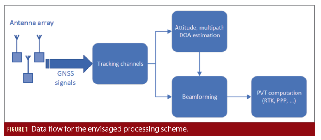
The overall data flow is shown in Figure 1. The assumption is all navigation signals under consideration are acquired and tracked in tracking channels that are synchronized, i.e. employing vector tracking, and all antenna element channels for the same frequency and satellite share the same Numerically Controlled Oscillator (NCO).
Using Double Differences (DD) of Prompt Correlators (DDPC), the attitude of the array platform is estimated. This information is passed to the beamforming unit, which directs the array gain toward the satellite and mitigates MP. The beamforming unit delivers accurate code pseudorange and carrier phase measurements, which are then delivered to a conventional position, velocity and time (PVT) estimation algorithm.
This work focuses on the estimation process of attitude and MP Direction of Arrival (DOA) for a few specific array configurations (standard Uniform Rectangular Array (URA) geometry and AR headset) considering various frequency bands and satellite constellations. The use of the obtained attitude and MP DOA for the beamforming and PVT is discussed, qualitatively indicating the need for further research. In contrast to other works on beamforming listed in the references, Multipath and Attitude Estimating Phase Lock Loop (MAEPLL) simultaneously exploits signals from all satellites by explicit consideration of all DOA vectors and the platform attitude.
The work on MAEPLL was motivated by the publications of Zorn and Brachvogel, who introduced the sub-optimum platform-driven array concept [3,4]. MAEPLL extends this concept by using DDPC to minimize the need for hardware calibration.
The MAEPLL Concept
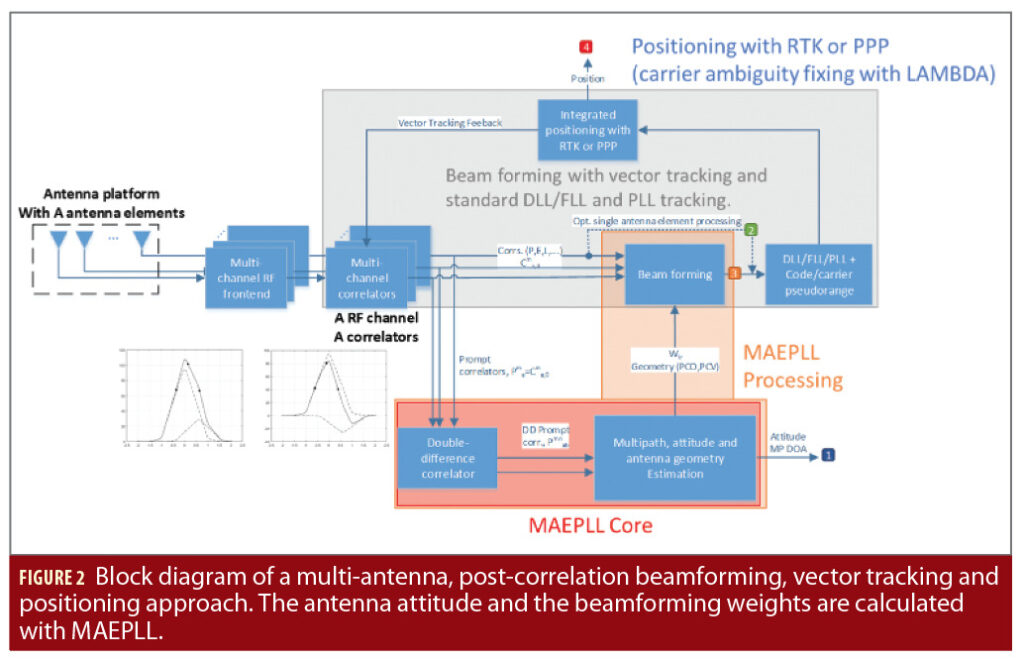
The MAEPLL technique is meant to be integrated into a vector tracking (VT) receiver. The VT ensures prompt correlator (PC) values are available for all signals and satellites (even during partial blocking of the signals). The MAEPLL processing includes the MAEPLL core and the beamforming. It can be seen in Figure 2.
In the MAEPLL core, the DDPC values are used to estimate the platform attitude and the DOA of the MP wave fronts. The beamforming stage receives as input the correlator values from the VT and applies a non-adaptive/geometric beamforming to enhance the Line-of-Sight (LOS) signal and suppresses the MP components. Non-adaptive/geometric beamforming means the array steering vector is only set according to the geometrical conditions.
After the beamforming, the enhanced correlator outputs are used in special Delay Lock Loop (DLL) or Phase Lock Loop (PLL) filters that generate code pseudoranges and carrier phases measurements out of the beamformed correlation values. The estimation of PVT can be performed using well-known positioning techniques like Single Point Positioning (SPP), Real Time Kinematic (RTK) or Precise Point Positioning (PPP).
In Figure 2, the block diagram of the MAEPLL receiver architecture is sketched. The red area indicates the core of the MAEPLL technique. This article focuses only on the MAEPLL core functionality, with the other parts assumed to work as intended. Dual-frequency signal processing is used to strengthen the combined estimation process of MP DOA, platform attitude and array geometry.
The antenna array is a calibrated multi-antenna array with known geometry and consists of A antenna elements with the antenna element a∈{1,…,A} and the antenna element displacement vectors da in the Antenna Reference Frame (ARF). The antenna reference point equals the first antenna element a=1. The antenna receives N satellite signals of the satellites n,m∈{1,…,N}, while the highest satellite is also the reference satellite for the double differencing (DD). Each satellite transmits M signals on different frequencies with frequency slot μ∈{1,…,M}, frequency fμ and wavelength λμ. Each signal sa;μn transmitted from satellite n at frequency slot μ is tracked with the receiver using a NCO. The same NCO is shared for signals from different antenna elements a. Due to the slaved tracking, all received signals from different antenna elements a have a common base for the carrier ambiguities. The

is defined by:

with the prompt correlator (PC) modelled in the case of LOS-only conditions as

and the double differenced phase as

In these equations, the antenna index a represents the reference antenna element and the satellite index n represents the satellite reference index. The other antenna has the index b and the other satellite the index m. The amplitudes αa;μm in Equation 1 are real-valued and relate to the signal power C, and the coherent integration time Tcoh. The
is complex valued like the PC and P– represents the complex conjugate.
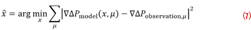
Considering not only LOS but also P MP signals and expressing the phase offset with respect to the reference antenna element and geometrical considerations (Figure 3, left), the prompt correlator value of Equation 2 can be approximated by

with p representing the signal component index (0 … line-of-sight; 1, 2, … MP), αp;μm the signal component amplitude and kpm the angular wave number (kpm proportional to unit-vector in direction to satellite m). The parameter kμ;pm is a function of the elevation and azimuth of the DOA kμ;pm (θm,Φm) w.r.t. to the platform attitude. For the LOS signals, elevation and azimuth can be derived from the platform position and attitude. For the MP signal, azimuth and elevation need to be estimated. The DOA can be expressed in the ARF or in the East/North/Up (ENU) frame. ϕ1;μ;pm equals the phase of wave front p at antenna element 1 (Figure 3).
Equation 4 states that the effectively impinging electromagnetic wave at antenna element a is the superposition of the LOS and the MP waves, each with a different amplitude and the phase being defined in relation to the phase of the respective signal phase at antenna element 1. It is also assumed that the received amplitude is independent from the antenna elements a, b and the carrier index μ. With this assumption, the double differenced prompt correlator can be modeled as

with P, Q, R and S as signal component indexes of the four PC values forming the DDPC. The equation represents a relation between DDPC values, the attitude of the antenna platform, the wave vectors of potentially present MP signals and the signal amplitudes. If only the line-of-sight signal is present (P=Q=R=S=0), it reduces to

The vector of unknowns in Equation 6 is the platform attitude (yaw, roll, pitch) and the LOS amplitudes. If each LOS signal is accompanied by a MP signal, the vector of unknows is extended by MP amplitude, elevation, azimuth and phase delay.
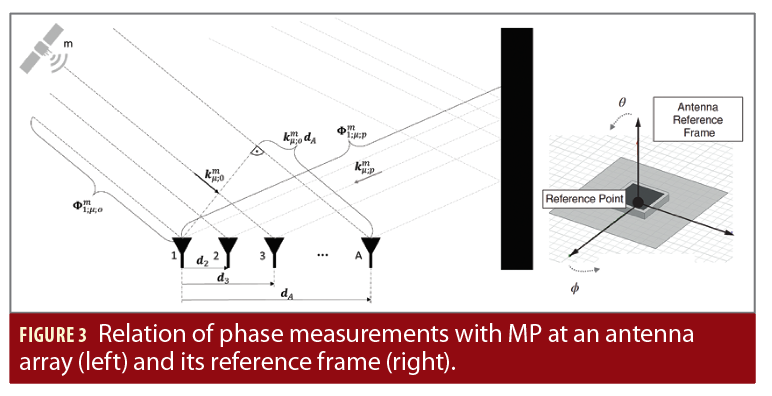
Within the MAEPLL core, the model (5)—or (6) if only LOS is assumed—is fitted to the actual DDPC values obtained after each integrate and dump period. A non-linear least squares estimation process is carried out, expressed as
with x representing the state to estimate and xˆ the resulting estimates. ∇ΔPmodel represents the DDPC values computed by (5) or (6) and ∇ΔPobservation,μ represents the DDPC values coming from the tracking channel. Whereas a final MAEPLL implementation will continuously track the vector of unknowns, in this article only the behavior at a single epoch is investigated (snapshot approach). It is reasonable to assume the continuous tracking of x is well possible as it will be shown that (7) converges well. This is because for continuous tracking, each integrate and dump epoch will refine the estimate of x and thus provides good initialization values for the next epoch. On contrast, for the snapshot approach investigated here, the minimization of (7) starts from worse initial conditions.
Considered GNSS and LEO-PNT scenarios
The resurgent interest and promised potentials of new dense constellations of LEO satellites operated by business-oriented private companies has been a driver for considering a non-standard GNSS space segment as an additional scenario to frame the MAEPLL design. Unlike the well-known legacy medium Earth orbit (MEO) GNSS, the panorama of the LEO constellations is far from being consolidated. Number of satellites per constellation, orbital radii and planes, as well as frequency planes, power and services allocations and signal interfaces are not defined yet in many intended constellations. This translates to several interesting degrees of freedom. Whereas LEO PNT service is considered complementary, not alternative to the legacy MEO GNSS by the authors, MEO and LEO constellations are evaluated separately in this work to better understand the real differentiators for the effectiveness of MAEPLL, namely the impact of the geometric diversity provided by MEO GNSS and the LEO constellation.
The number of satellites orbiting in such LEO constellations may vary from a few tens, principally in constellations designed for Earth Observation, to several thousand when the business purpose is broadband internet services [2,5]. The orbital altitude may vary from a few hundreds to about two thousand kilometers. The complementary PNT service is assumed to be offered to the AR user together with a broadband data connection through a satellite constellation intended for broadband communication services.
For reference, the orbital altitude is assumed 1,200 km (orbital radius minus average Earth radius), with global coverage of the Earth offered by 1,200 satellites appropriately spread along 30 orbital planes. With some further hypothesis on the antenna footprint discussed later, these assumptions will be important to consider the number of visible satellites for a user on the Earth surface and their geometry with respect to the user (i.e., the Geometrical Dilution of Precision, GDOP) [5]. The simulation of the motion of such a reference LEO constellation along its orbit allows us to appreciate the benefit it offers the ambiguity fixing problem. It is worth noticing the obtained results are representative of the possible variations of the average altitude in the ‘upper-LEO’ range, which remains roughly 20x lower than the GNSS MEO altitude range.
The PNT payload generating the ranging signal was assumed to share resources with other services, in particular the nadir-pointing surface with the antenna and the available transmission power. For the antenna, it is reasonable to assume a spot-beam arrangement, driven by the principal communication purpose that targets high throughput into small areas. For simplicity of simulation, such a radiation pattern is modelled as an elevation cut-off angle at the user receiver equal to 30°. On average, the number of visible LEO satellites in open sky is similar to the number of GNSS MEO satellites (multi constellation) but the user GDOP is worse. The LEO satellites tend to be clustered toward the zenith because of the cut-off angle.
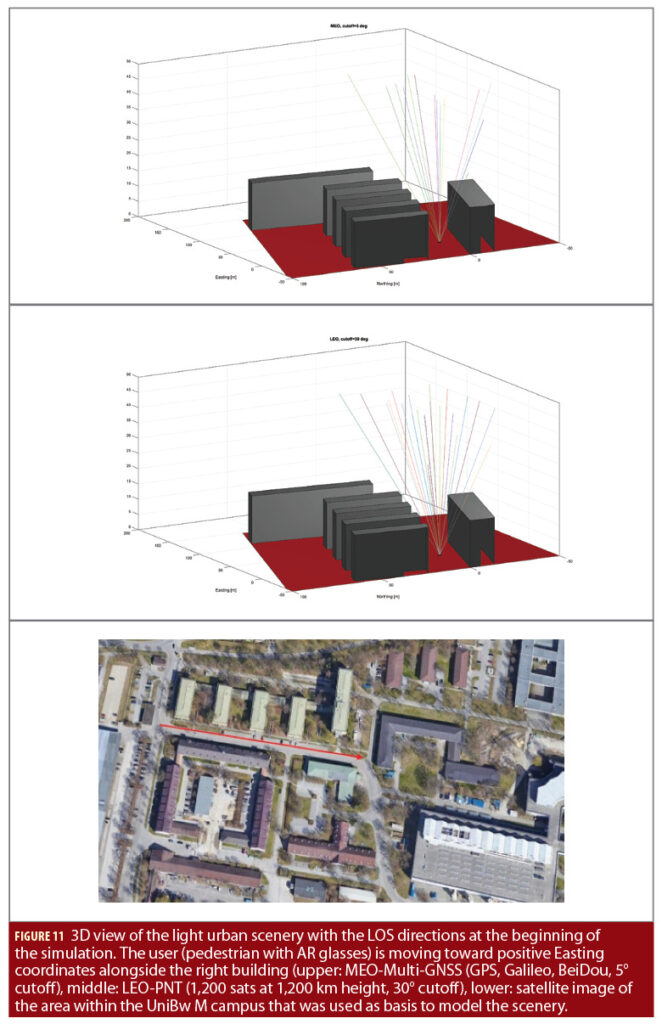
In the opposite case, in dense urban conditions, the visibility is slightly better for LEO satellites (Figure 11), although their visibility interval is quite short because of their high speed. As anticipated, the faster variation of the geometry of the LEO satellites with respect to one of the MEO satellites is expected to be highly beneficial to the ambiguity fixing problem the more it contributes to a faster decorrelation of the estimable parameters in the state vector. Furthermore, MAEPLL obtains great benefit from the LEO specific geometry.
The ranging signal baseline assumed for the LEO service is like legacy GNSS, which is to make fair evaluations in uniform conditions. However, an interesting element to consider is the frequency allocation of the LEO PNT signals. Starting from a regulatory point of view, it is possible to identify several tens of available frequency bands offering advantageous properties. The frequencies allocated to Radio Navigation Satellite Services (RNSS) offer the best match for a new satellite-based navigation service. However, the associated bands are almost saturated with already existing systems, which encourages considering other services, like Radio Determination Satellite Service (RDSS), Maritime Radionavigation Satellite Service (MRNS), if a common interest can be found in the maritime community for the use of the LEO-based service and even Mobile Satellite Service (MSS), following the Iridium precedent. The prioritization of the possible bands ranks on top RNSS and RDSS, then the primary services status, which guarantees good protection in their respective bands, then the bandwidth. For example, the sub-GHz allocations do not offer enough bandwidth for high precision applications. High-potential allocations for LEO-based positioning services require at least 20 MHz signal bandwidth and two carrier frequencies, a diversity helpful when accuracy is a target. For this article, signals in RNSS L and S-band have been considered.
The transmission power is chosen to achieve similar C/N0 values to the MEO-GNSS at user location and is substantially lower than MEO-GNSS because of the lower orbital height. Furthermore, this reduced transmission power is compatible with a realistic on-board power budget for such satellites. Signals are assumed to be transmitted as right-handed circular polarized waves (RHCP).
To model multipath effects in a frequency independent way, a new and simple signal reflection and blocking model was developed. The scenery shown in Figure 11 is adopted for the study. The ground (red plate) is modelled as concrete and signal reflections are computed accordingly. Applying the concept of dominant reflectors, metal spheres proportional to the size of the plane are placed within the center of each plane forming the buildings. The radar cross section theory is used to compute the power of multipath signals. Ground reflection and radar cross section are concepts with well understood frequency dependence and thus can be applied to this investigation.
Understanding MAEPLL
The main goal of this article is to demonstrate if the model shown in Equation 5 is suitable for realistic GNSS/LEO scenarios and if it can properly model the correlation values. For this reason, a variety of scenarios were simulated, including open sky conditions with and without ground MP, as well as varying signal power, adding transmitting frequencies, assuming different initial guess errors and antenna element gain pattern. Changing the listed parameters of the simulation makes it possible to study the performance and behavior of the MAEPLL core algorithm. Within this article only two representative results are illustrated, which show the estimation process and indicate capabilities and limitations of the approach nicely [6].
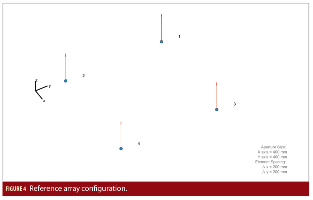
In the first test case, the reference array configuration shown in Figure 4 was assumed. It is a standard URA geometry with four antenna elements and an element spacing of ~19 cm. A GPS C/A like ranging signal on the L1 frequency, at S-band, a receiver processing with 10 MHz receiver frontend bandwidth and 10 ms coherent integration time was assumed. A combined GPS, Galileo and BeiDou constellation was assumed but with all satellites broadcasting the signal structure at L1 and S-band. Around 27 satellites were visible in open sky conditions including both MEO-GNSS and LEO. An omnidirectional antenna gain pattern for RHCP and LHCP was assumed, as this is a good representation of low-cost antenna elements currently used in smartphones, providing nearly no protection against MP from the ground [7].
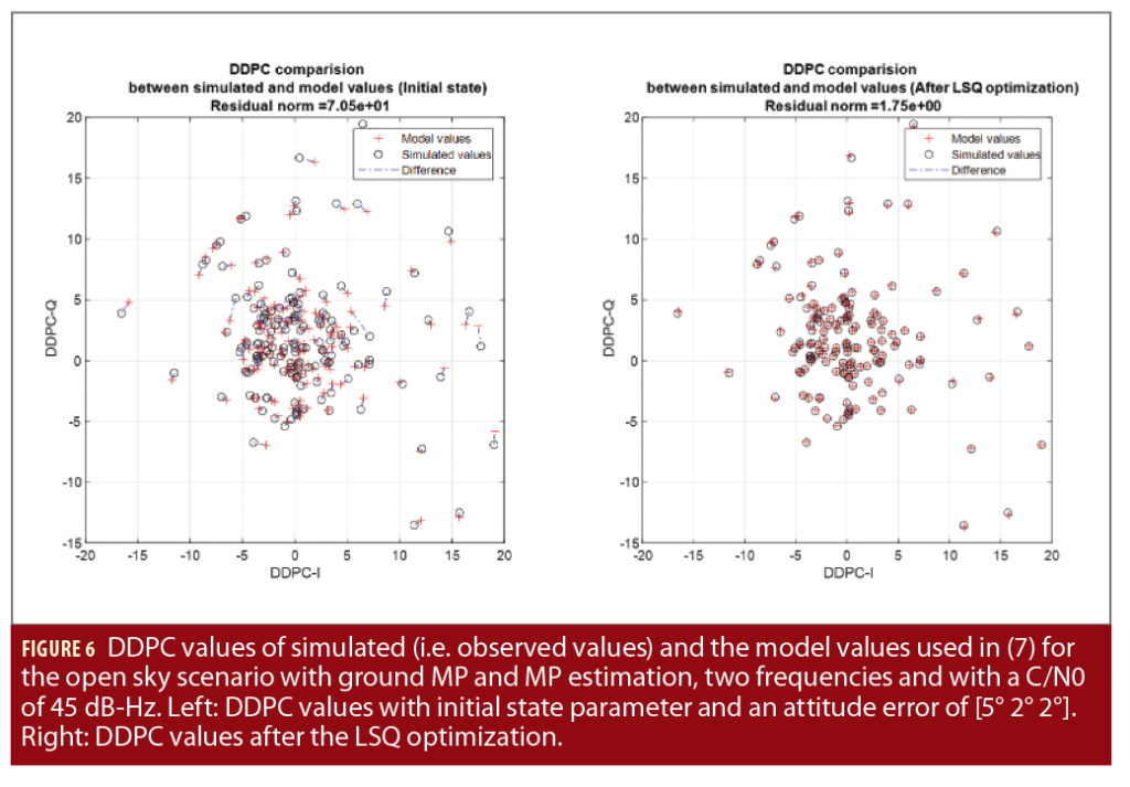
An open sky scenario with additional ground MP signals (ground material is concrete) is used to simulate the prompt correlator values, which are then used to compute the DDPC values. A LOS signal power of 45 dB-Hz was assumed. The MP signal power depends on the reflection angle. The MAEPLL algorithm is set up to estimate array attitude, LOS amplitude, MP DOA, MP amplitude and MP delay. The MATLAB function lsqcurvefit is applied, using the indicated initial state for the vector of unknowns as well as suitable chosen lower and upper bound limits. The estimated states for the attitude, the LOS amplitude, the MP DOA, the amplitude and the phase delay are then compared with the true state.
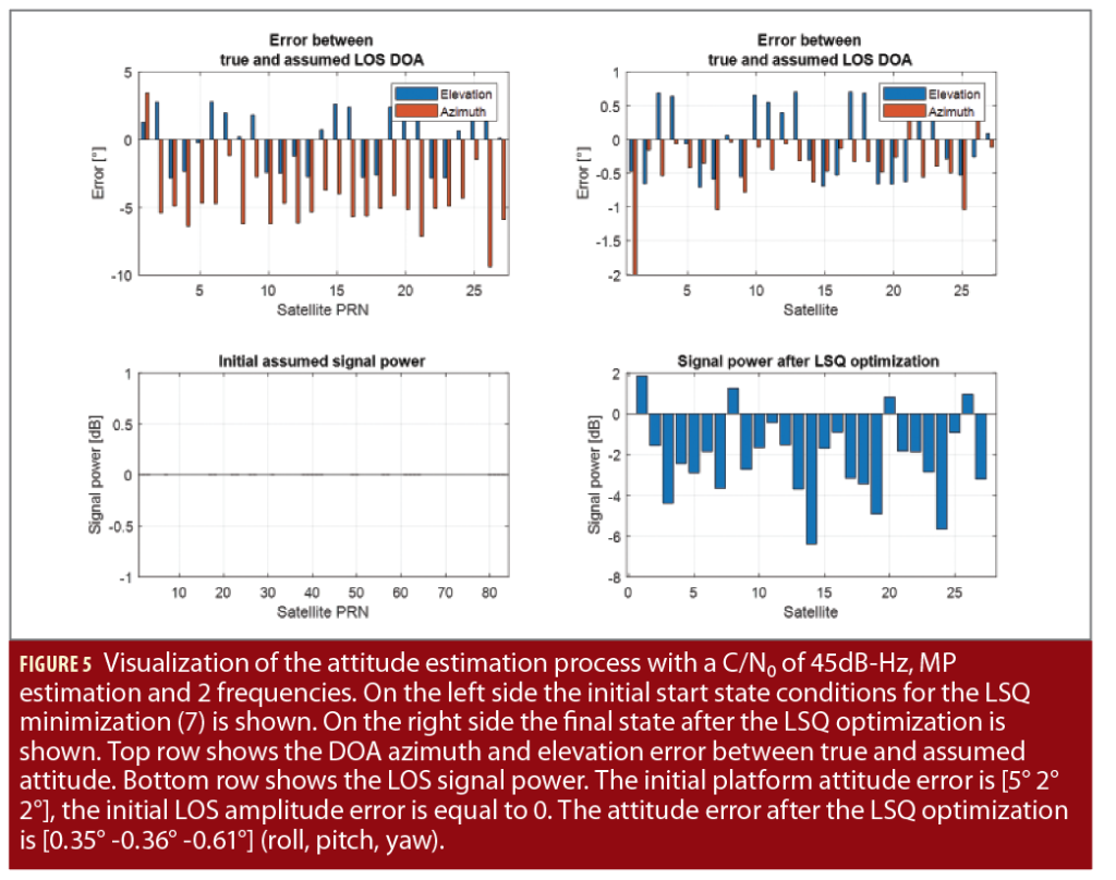
Figures 5-7 illustrate the results for the case where ground MP is present and MAEPLL estimates the parameters for one MP component along with the attitude and the LOS amplitudes. Figure 5 shows the attitude estimation works properly (the attitude error is [0.35° -0.36° -0.61°] for roll, pitch and yaw), even though strong ground MP components are present. The antenna does not damp the ground MP as an isotropic antenna pattern is used (even for LHCP) and concrete is a good reflector from RHCP to LHCP.
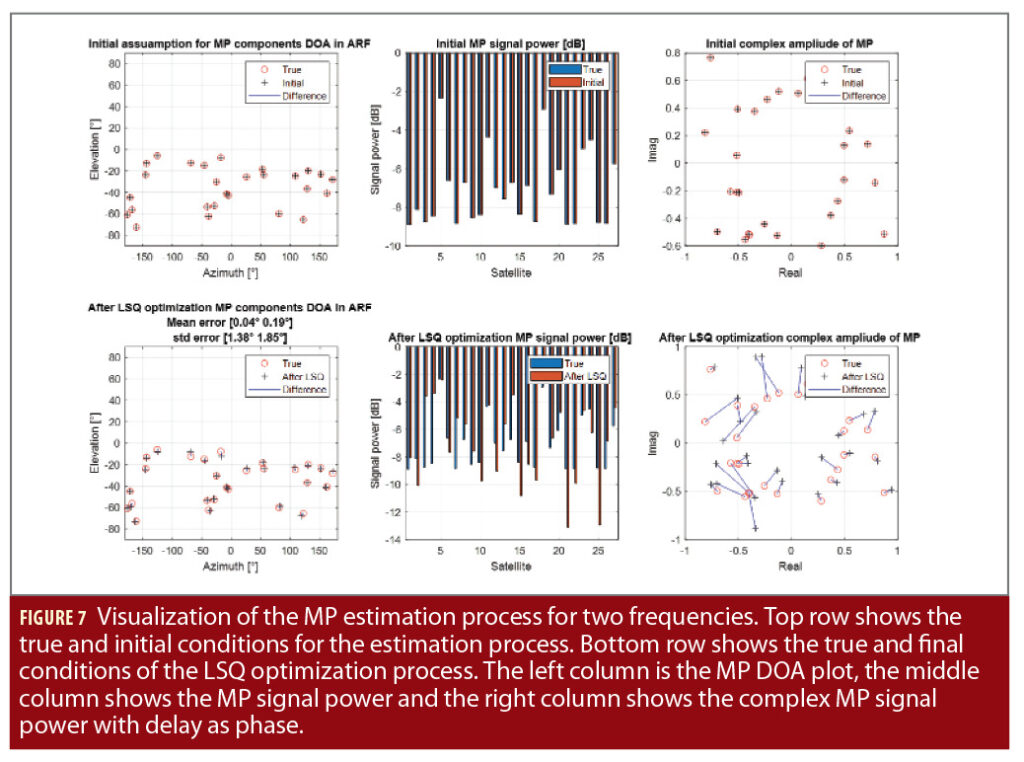
The figures also show the MAEPLL algorithm adapts the LOS signal power parameter to reduce the residual norm of the DDPC values in (7) and tries to compensate for the MP influence. The optimization convergence requires 26 optimization steps. Already after 4 optimization steps, the bulk part of the convergence is achieved. If no MP parameters are estimated, the convergence needs fewer steps. This indicates the MP parameters are not converging as accurately as the attitude and LOS amplitude parameters. This also can be seen in Figure 7, where the MP parameters for the initial conditions are visualized on top.
In this analysis, the initial MP parameters were set to the true MP parameters. At the bottom of Figure 7, the MP parameters after the LSQ optimization are visualized. They do not match the true values after the optimization. It seems the MP phase delay is a critical parameter that is not converging properly. The MP phase delay is displayed as the phase in the right complex plane plot of Figure 7.
When estimating the MP parameters, the optimization algorithm has more dimensions of freedom to compensate the scattering of the DDPC values because of the presence of thermal noise. It seems the MP parameters are more sensitive to this noise. Higher C/N0 values mainly result in a better MP parameter estimation but not in a better attitude estimation. It was also found the use of a second frequency is mandatory for the challenging MP DOA estimation process. An open question regarding the MAEPLL estimation process is if a second frequency below or above the L1 frequency has a different impact.
Applying MAEPLL for AR Headsets
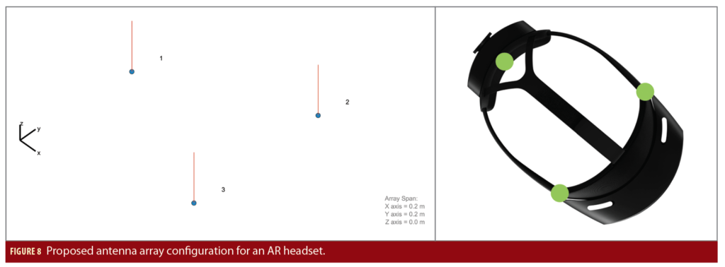
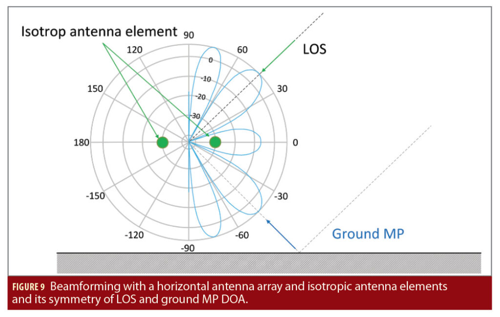
The MAEPLL technology was then applied to an AR headset case using the antenna configuration shown in Figure 8, where a triangular arrangement of the antennas seems to be most suitable. The arrangement is clearly driven by platform constraints and not by the wavelength. Again, an isotropic gain pattern (for LHCP and RHCP) is assumed as this seems to be the most realistic case for low-cost antenna elements. Such an array is symmetric with respect to the plane of the three antenna elements and thus ground MP might not be mitigated if this plane is horizontally oriented, as can be seen in Figure 9.
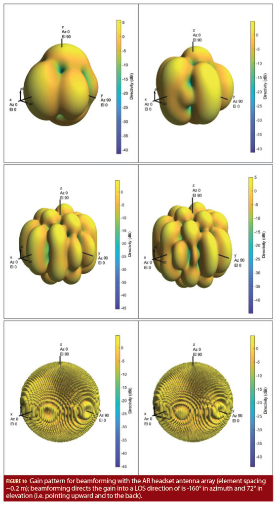
To gain insight on the beamforming capabilities, the antenna array gain patterns were computed under the idealized non-adaptive/geometric assumption that the array is fully calibrated and the gain is focused toward the LOS signal. For each considered frequency band, two different frequency channels are chosen and the array gain patterns are shown in Figure 10. For L-band and S-band, the maximum gain (bright yellow color) is achieved frequently, and MP suppression (without nulling) can reach values up to -15 to -20 dB. For L- and S-band the width of the main lobe is wider than the MAEPLL attitude estimation accuracy, meaning that by purely geometric means a focus to the LOS signal can be achieved. The situation is much different with the Ku/Ka-band, where the lobes are pencil-sharp and it is unlikely the attitude accuracy is sufficient enough to direct the main lobe toward the satellite.
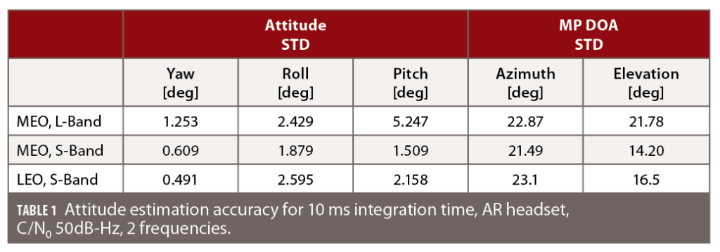
A Monte-Carlo simulation for the array in Figure 8 was set up and different sets of correlation values were generated for a light urban environment shown in Figure 11. The scenario mimics an AR user carrying the headset and walking on a sidewalk along a building. The simulation was conducted for L-band and S-band, each time assuming two frequencies, as in Figure 10, with a GPS C/A-like modulation. A LOS signal power of 50 dBHz and an integration interval of 10 ms was assumed for the snapshot processing. For each set, the estimated values are compared to the true values. Finally, the accuracy of the estimation process was assessed. The results are summarized in Table 1. Those results are also representative for other simulated scenarios. For MEO, the GPS+Galileo+BeiDou constellation was considered, and the 1,200 satellite internet broadband constellation at 1,200 km height was considered for LEO.
It was found that the attitude estimation accuracy is already high in L-band, considering only a 10 ms interval of the received GNSS signal is used. Comparing the attitude results of the L-band with the S-band, an improvement of the attitude estimation is visible (S-band results show more accuracy). An improvement in the order of 0.2°–3° was also visible for other simulations that were conducted and is dependent on the constellation and antenna geometry. It also can be seen that the MP DOA estimation improves by changing from the L- to the S-band. When doing the same simulation at 40 dBHz (instead of 50 dBHz), the MP DOA estimation accuracy improvement between L-band and S-band was even more expressed. On the other hand, when a quadratic 4-element array with ~1 m side length (e.g. for an antenna array on a car’s roof top) was tested, the L-band MP DOA results were better than the S-band results. This indicates the influence of the antenna geometry is important, and that having the bigger element distance becomes a disadvantage.
The results for the attitude estimation in all simulated cases are accurate to within a few degrees. Multiple reflections per signal were present, but only one MP component was estimated. The MEO constellation gives slightly better attitude results than the LEO constellation, although for MEO and LEO approximately the same number of signals were visible. However, the MEO cutoff is set at 5° while the LEO cutoff is at 30°. The MP DOA estimation works with an accuracy between 20° to 30° in azimuth and elevation. The performance is similar for LEO and MEO. The MP DOA accuracy can be further improved by increasing the C/N0.
Toward Beam-Forming and PVT
The simulations indicate the MAEPLL core works very consistently. This is most likely because the DD process eliminates any hardware delays and allows using a very direct model relating geometric parameters to the prompt correlator values. In the next steps, the estimated parameters shall be applied for conducting non-adaptive/geometric beamforming to produce multipath reduced code pseudoranges and carrier phases that are finally used in precise positioning algorithms like RTK or PPP. The process of beamforming and precise positioning has been simulated for a multitude of scenarios and settings with detailed results that cannot be illustrated within the scope of this article, which instead presents a qualitative discussion to outline the strategy, general findings and difficulties.
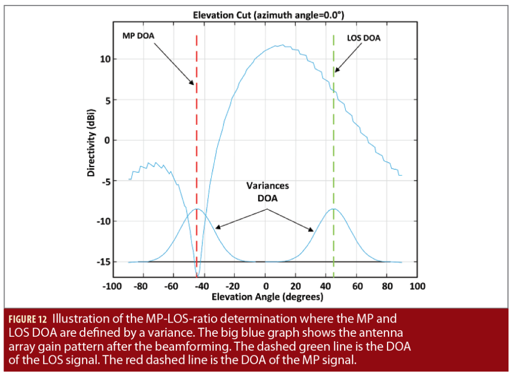
The envisaged beamforming strategy should make use of the estimated geometric parameters (attitude and MP DOA) and maximize the array gain toward the LOS and place one Null in the direction of DOA of the estimated MP (only one MP is estimated per signal; it is assumed it corresponds to the strongest MP). Because platform attitude and DOA have estimation errors, the DOAs assumed by the array will somehow deviate from the true DOAs (Figure 12). A MP DOA error will misplace the Null of the array and substantially degrade the MP mitigation performance. Furthermore, not just a single MP can be present. Sometimes, there are multiple MPs or no MP present. If one would estimate DOA of further multipath components, those errors would be even larger, and placing Nulls into those directions even more difficult. On the other hand, LOS DOA accuracy is very high and compatible with the width of the main lobe of array, at least for L- and S-band.
A further difficulty in this concept of geometric beamforming is the need to work with undifferenced (i.e. raw) correlator values (in contrast to the MAEPLL core). Those values depend on hardware delays coming from LNAs and RF filters. Those delays need to be either known from calibration or estimated within another processing step. This aspect was not considered by the authors.
Overall, it seems the simplicity and robustness of the MAEPLL core is somehow lost when moving further along the processing chain. Adaptive beamforming algorithms could of course be used, but they are less robust as they estimate hardware delays in addition to the attitude and DOA, or they consider only a single satellite and thus loose the geometric diversity introduced by multiple satellites. They might even have difficulties distinguishing LOS from strong MP reflections in non-LOS conditions, as they work solely in the domain of the array steering vector and do not relate those parameters to a geometric direction. Thus, including the geometric information obtained via the MAEPLL core into an adaptive beamforming algorithm might be a promising direction of future research.
Nevertheless, the beamforming scheme of LOS power maximization and placing one Null into the assumed MP DOA was applied and the resulting LOS and MP components evaluated using multipath error envelopes for code and carrier. Code and carrier variances due to MP were then combined with thermal noise variances. Assuming all measurement errors are captured by this process and remain bias-free (which is of course a simplification), the float positioning accuracy was calculated and the ability to correctly resolve the carrier phase ambiguities for PPP was computed by the Ps-LAMBDA toolbox [8].
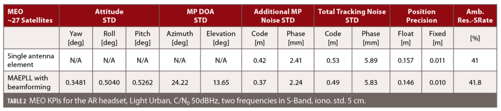
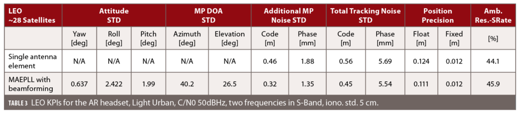
A time span of 5 s was considered to test fast ambiguity fixing but still exploit the variation in the sky plot of the LEO constellation. Exemplary results of those simulations are shown in Tables 2 and 3, focusing on the AR headset when using the S-band in the light urban scenery of Figure 11. The differences between the MEO multi-constellation and the LEO constellation was investigated in those simulation runs. An ionospheric delay uncertainty of 5 cm was assumed, which could be achievable by future high-resolution iono models. Code and phase biases were assumed to be perfectly known. It was observed that the ambiguity success rate for PPP-like processing depends largely on the ionospheric uncertainty. The attitude accuracy is comparable to commercially available low-cost GNSS-INS systems making use of MEMS sensors. They use only a single antenna but require proper initialization phases (coarse alignment). Our method provides an instantaneous attitude estimate.
Discussing the Impact on PVT, Lessons Learned and Further Research
The conducted studies on the use of MAEPLL in various scenarios for various constellations (MEO, LEO) and frequency bands showed the snapshot-based attitude estimation using MAEPLL is very robust and accurate under all kinds of environments and conditions when the antenna geometry is large and even if the element spacing is >λ. This gives design flexibility for large antenna arrays on cars. The AR headset with its closer element spacing of <λ/2 (in L-Band) didn’t show the same good attitude error but was still in the range or below the initial 5° of all tested scenarios. In S-Band, the element spacing better matches the AR headset case and the attitude standard deviation error is below 1.5°. It shall be noted that AR especially requires a robust and precise attitude estimation of the headset to overlay the camera image with the real world in an open world context. Angular errors might be more important than positioning errors. Current AR headsets provide framerates of 60 Hz to 120 Hz, which would be compatible with our snapshot duration of 10 ms. Nevertheless, IMU aiding is clearly useful to further stabilize and smoothen the attitude estimate.
The simulations showed the beamforming main lobe beam width and the attitude estimation accuracy depend on the element spacing. If possible, the element spacing has to be chosen in combination with the used frequencies so it’s large enough to allow an accurate attitude estimation and simultaneously be close enough to produce a wide enough main lobe to cover the LOS DOA uncertainty in the non-adaptive/geometric beamforming process. With a matching array geometry, MAEPLL and non-adaptive/geometric beamforming can be used to focus on the LOS signal. Because the array geometry also depends on the platform, a dependency between application and frequency band is established.
The tested LEO constellation uses a higher elevation cut off angle of 30° and showed the same accuracy of the attitude estimation as the MEO constellation with 5° cutoff. The LEO constellation will thus be superior in deep urban scenarios where MEO will also suffer from an increased GDOP. The combined MEO-GNSS and LEO constellation will provide the best results.
The MP DOA estimation is very sensitive to the C/N0 and the overall MP conditions. For only a single strong MP component (e.g. if only ground multipath is present and the array geometry does not exhibit an unfavorable symmetry) with a C/N0 >60 dBHz, the MP DOA can be estimated with a standard deviation of <10° (Figure 7 lower left plot),which is sufficient for MP DOA nulling and an improvement of the MP-LOS power ratio. For other more realistic conditions with many reflections per satellite, the MP DOA accuracy is insufficient for direct MP DOA nulling. The LEO constellation has no significant improvement on the MP DOA estimation.
A second frequency improves the attitude and MP DOA estimation in some cases by an order of magnitude but was still insufficient for direct MP nulling. The use of different frequency bands also has an influence on the attitude and MP DOA estimation. Overall, better nulling algorithms and better array geometries need to be studied to enable the entire possibilities of beamforming. An interesting solution to study would be a combination of a non-adaptive/geometric beamforming for the LOS signals and an adaptive beamforming for the MP signals, combining the benefits of both approaches.
Apart from these drawbacks, the considered non-adaptive/geometric beamforming for LOS and MP has improved the code and phase accuracy to some extent in an urban scenario. The LEO constellation can benefit from the fact it has no low elevation satellites and therefore no strong and shallow ground MP components present. The LEO constellation partly improves the ambiguity resolution success rate even though the constellation geometry is not as good as the MEO multi-constellation due to the different cut-off angle. Both constellations have approximately the same number of visible satellites in open sky. The higher LEO satellite dynamic compensates for the lack of geometry and even improves the results if two epochs are considered with a time difference of only 5 s.
Related to ambiguity resolution, the L-band signals have the longest signal wavelength. Therefore, the ambiguity resolution can be resolved relatively easily compared to the other tested bands with shorter wavelengths. Under otherwise similar conditions, the ambiguity resolution success rate will always be higher for L-band signals than for S-band or even Ku/Ka-band signals. However, the beamforming capabilities can be improved for the S-band by more suitable antenna array geometries, which can then also improve the ambiguity resolution success rate. The best frequency band selection strongly depends on the application, the imposed array geometry and the antenna element distances. For autonomous driving with the array mounted on the roof top, L-band or lower frequencies should be chosen. For the discussed AR headset, the S-band seems to fit quite well. For array applications in a smartphone, the C-band could be interesting. It is reckoned that the Ku/Ka-band wavelength is too short to be used in a beneficial way with MAEPLL for the mentioned use cases. However, an application that requires smaller array dimensions still can be an interesting scenario for the Ku/Ka-band as well as for pure use of adaptive beamforming. It must be noted that the use of an array to compensate the free space loss occurring at higher frequency bands has not been discussed in this study and instead a constant C/N0 value was assumed.
Overall, it was difficult to isolate, quantify and distinguish the influence of the different parameters on the ambiguity resolution success-rate based on the performed simulations. However, under the same conditions, MAEPLL plus non-adaptive/geometric beamforming can improve the ambiguity resolution success rate compared to a single antenna element.
Acknowledgments
The presented work was conducted within an ESA funded study “INNUNEDO (INNovative User receiver processing and ENhanced signals in gnss Domain),” ESA Contract No. 4000128514/19/NL/CRS. Various other consortium members contributed to the simulation tool chain. Their contribution is highly acknowledged as well as the discussions with ESA staff. The content of the article is research reflecting solely the authors’ view and by no means represents the official ESA view or the one from Galileo or EGNOS Project Offices.
References
(1) Philipp A. Rauschnabel, Reto Felix, Chris Hinsch, Hamza Shahab, Florian Altl “What is XR? Towards a Framework for Augmented and Virtual Reality”, Computers in Human Behavior, vol. 133, 2022.
(2) T. Reid, A. Neish, T. Walter, and P. Enge, “Broadband LEO constellations for navigation,” Journal of The Institute of Navigation, vol. 65(2), 2018.
(3) S. Zorn, T. Bamberg, M. Meurer, “Accurate Position and Attitude Determination in a Jammed or Spoofed Environment Using an Uncalibrated Multi-Antenna-System,“ Proceedings of the 2018 International Technical Meeting of The Institute of Navigation, Reston, Virginia, January 2018, pp. 690-702.
(4) M. Brachvogel, et al. “A new array concept using spatially distributed subarrays for unambiguous GNSS interference mitigation in automotive applications,“ Navigation 67.1 (2020): 23-41.
(5) R. Morales-Ferre, E.-S. Lohan, G. Falco, E. Falletti “GDOP-based analysis of suitability of LEO constellations for future satellite-based positioning.” 8th Annual IEEE Int. Conf. on Wireless for Space and Extreme Environments (WISEE 2020), 12-14 October 2020 (Virtual).
(6) Maier, Daniel S., Pany, Thomas, “Multipath and Attitude Estimation Phase Lock Loop for Antenna Array Signal Processing,“ Proceedings of the 34th International Technical Meeting of the Satellite Division of The Institute of Navigation (ION GNSS+ 2021), St. Louis, Missouri, September 2021, pp. 3402-3421.
(7) Sharma et al., “Smartphone-based GNSS Positioning – Today and Tomorrow”, Sept. 2021, https://insidegnss.com/smartphone-based-gnss-positioning-today-and-tomorrow/
(8) S. Verhagen, B. Li, “PS-LAMBDA software package“, URL: https://www.tudelft.nl/citg/over-faculteit/afdelingen/geoscience-remote-sensing/research/lambda/lambda
Authors
Daniel S. Maier received a bachelor in Physics in 2015 and a master in Applied and Engineering Physics in 2017 from the Technical University of Munich (TUM), Germany. Between 2017 and 2021 he has been a research associate at the Institute of Space Technology and Space Applications of the “Universität der Bundeswehr München” with research topics including GNSS signal generation, signal authentication, signal performance analysis, antenna array processing and spoofing detection. Since 2022 he works as navigation system engineer for GNSS application at Airbus Defense and Space.
Mathias Philips-Blum (M.Sc.) received his M.Sc. in Geodesy and Geoinformatics from the Leibniz University of Hannover, Germany in 2012. In 2017 he joined the Institute of Space Technology and Space Applications (ISTA) of the University of Armed Federal Forces Germany in Munich. He is currently a Ph.D. student working on algorithms for navigation in space and on Earth, and on the topic of simulation of test environments.
Thomas Pany is a professor at the Universität der Bundeswehr München where he leads the satellite navigation unit of the Institute of Space Technology and Applications (ISTA) being part of the Space Research Center (FZ SPACE).
Emanuela Falletti (Ph.D.) is technology specialist for the Space & Navigation technologies in the AI, Data and Space Division of the LINKS Foundation, in Torino, Italy. She received M.Sc. and Ph.D. degrees in Telecommunications Engineering from Politecnico di Torino in 1999 and 2004 respectively. Her research has covered array signal processing and wireless propagation channel modelling. Currently she has almost 15 years experience on software radio and digital signal processing techniques and algorithms for advanced GNSS receivers, in particular for interference and spoofing detection and mitigation, multipath mitigation and signal simulation. Dr. Falletti is author of more than 40 scientific papers in peer-reviewed journals.
Paolo Zoccarato holds a Ph.D. in science technology and measurements for space on precise orbit determination from the University of Padova, Italy. He worked at Curtin University as a PostDoc on PPP-RTK and in Trimble TerraSat GmbH on VRS and RTx. He is a radio-navigation engineer consultant at ESA/ESTEC, contributing mainly on real-time reliable high-accuracy positioning for different GNSS receiver types, sensors, environments and systems.
Francesca Zanier received her M.Sc. in telecommunications engineering and Ph.D. from the University of Pisa, Italy. In 2009, she joined the European Space Agency, ESTEC, Noordwijk, The Netherlands, where she is currently a Radionavigation System Engineer in the Radio Navigation Systems and Techniques Section of the Technical Directorate. Her primary areas of interest include signal processing, estimation theory, GNSS receivers and navigation applications.