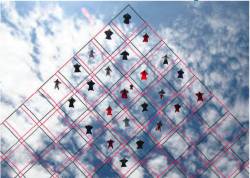
 FIGURE 1: Competitive group skydiving is currently judged by overlaying a grid on a photo and evaluating location of divers within its cells. Photo by Mark Harris.
»NovAtel Inc. wingsuit video
In 1589, at the age of 25, Galileo Galilei toiled up the 294 steps of a 55-meter bell tower in Pisa, Italy, where he was tutoring math students at the time.
According to his pupil and later biographer, Vincenzo Viviani, Galileo carried with him two cannonballs, one twice the weight of the other. When he reached the top of the tower, he went to the lower balcony of the tilted structure and dropped the two balls simultaneously.
By demonstrating that the cannonballs’ time of descent was independent of their mass — they reached the ground at the same time — Galileo thus disproved Aristotle’s theory of gravity, which states that objects fall at speeds relative to their mass.
Although the truth of Viviani’s account is disputed, it does support the notion that throwing things from high places occupies a venerable place in the history of scientific discovery.
In any case, no doubt exists that on August 2, 2011, Andrew Levson climbed on board a Cessna 206 and, as the aircraft reached an altitude of 12,000 feet in the wide open Canadian skies over Alberta’s wheatfields, threw himself from the plane.
We know this occurred because Levson’s accomplishment was chronicled, not by an admiring biographer, but by four cameras along with position and heading data logged at 20 times per second. And he repeated the jump six more times that day.
Instead of two cannonballs, Levson carried two GNSS antennas and dual-frequency receivers incorporated into his specially tailored, skydiving wingsuit. After about 55 seconds of free-fall and another three minutes of precision gliding, he reached the ground safely.
Now, Levson was about the same age as Galileo when he dropped the cannonballs off the Pisa tower. However, Levson wasn’t trying to disprove some fundamental scientific law or principle by flinging himself from high places.
As befits his professional role as an applications engineer with NovAtel, Inc., Levson wanted to discover whether GNSS technology could help skydivers improve their performance in both individual and group competitions. Because, long before he graduated from the University of Calgary’s geomatics engineering department in 2007 and began work at nearby NovAtel, Levson had dreamed the dream of human flight.
Since 2000, Levson has made about 1,100 skydives, including 200 in aerodynamically advanced wingsuits — a particular passion for the last four years. Currently, he jumps about a hundred times per year, almost exclusively in one of the three wingsuits that he owns.
His motivation? “This is as close to human flight as I’m going to get.”
Wingsuit jumping is an advanced specialty within skydiving — definitely not something for beginners — and adds a level of complexity to an already inherently dangerous sport.
The late-model “Vampire 4” wingsuit that Levson used in the August jumps was manufactured in Slovenia by Phoenix Fly. Each suit is custom-tailored, using 14 key measurements of a customer’s body.
Sometimes characterized as “skydiving in a straitjacket,” a wingsuit limits the movement of a diver’s arms, legs, and overall mobility even as greater skills are needed to maintain control and fly the suit efficiently.
Depending on the organization with which he or she is affiliated, a skydiver has to make 200 to 500 regular jumps before being allowed to make one in a wingsuit.
For Levson, skydiving is less a hobby than a way of life. He met his wife skydiving, and most of his friends are skydivers. He is also a wingsuit instructor and freefall photographer.
GNSS & Skydiving
As with other extreme physical feats such as mountain-climbing, organizations have arisen that establish guidelines and monitor attempts to set individual and group records in skydiving. This can involve length, speed, and time of flight, and size and precision of mid-air formations.
According to Guinness World Records, the greatest distance flown in a wingsuit was a horizontal, straight-line distance of 23.1 kilometers (14.35 miles) by Shinichi Ito of Japan. On May 28, 2011, Ito jumped from a plane 9,754 meters (32,000 feet) above Yolo County, California, USA, and flew for 5 minutes 22 seconds.
Sports including car racing and distance running have already adopted GNSS technology to help measure and improve performance. Could the same thing happen with skydiving?
Individual distance records in the sport have in the past been measured by the position of the plane when the parachutist exits and the location of the landing site. “But the spirit of a [skydiving] record is the actual distance flown in freefall,” Levson says, “and for that you need GPS.”
The current official record for large group formation flying was set by 68 people in 2009 — with an unofficial mark established the previous year in a 71-way jump.
This coming September 19-23, a world record attempt will be made over Perris Valley, California: 100 wingsuits in the same formation. And, yes, Levson is planning to be there and is serving as Canadian representative for the effort.
Currently, the quality of group jumps is measured by taking a photo of the formation and overlaying a grid on the picture. (See Figure 1, inset photo, above.) Divers have to be within a certain distance of the borders of the diamond-shaped cells of the grid. As the formation gets bigger, it gets harder to keep everyone inside designated grid locations.
Real-time GNSS could help position and align divers for the execution of a record-setting effort: GPS-equipped participants placed on the corners of the diamond could provide audio alerts to let others in the formation know if they are getting out of their zones.
A Match Made in the Heavens?
A few years after joining the high-performance GNSS receiver designer and manufacturer NovAtel in 2007, Levson got the idea of leveraging the resources of the Calgary-headquartered company into his high-flying avocation.
“I thought of it as a way to combine two of my passions in life,” Levson says—GNSS and skydiving.
And when he raised the possibility with his colleagues, they—pardon the expression—leapt at the opportunity.
“I submitted a proposal to the Nov-Atel marketing team and they loved it!” Levson recalls. “They jumped all over it.”
And it wasn’t out of enthusiasm for skydiving per se, but the opportunity to assess performance of the company’s high-precision GNSS products under a set of unique high-dynamic conditions.
In effect, Levson and NovAtel colleagues conspired to turn his wingsuit into an aerial testbed for GNSS hardware and software.
In late 2010, Levson took a GNSS receiver board mounted in an enclosure on a personal skydiving trip to Arizona to test out the concept. This effort was undertaken with an extremely “quick and dirty” equipment setup, using nothing but readily available equipment.
Without a support team, the testing was very limited but showed that GNSS equipment mounted on a flying human body worked well in a jump. And such an effort requires a diverse set of skills and expertise.
“This activity has let me touch all these different places in the company that I wouldn’t normally get to,” Levson says.
Indeed, NovAtel has assembled a cross-departmental team to help shape and exploit the wingsuit testbed. In addition to Levson, team members and their roles include:
- Steve Bateman, VP of engineering, location scout plane pilot,
- Rob Watson, engineering design services, jump day set-up and data collection/analysis
- Samantha Poon, product marketing, data analysis and supporting documentation, market applications
- Thomas Morley, product validation, market application and technology benefits
- Curtis Jenkins, marketing communications, video production
- Lori Winkler, marketing communications, moral support.
“When evaluating the results [from Levson’s proof of concept jump], we continued thinking about how to extract more useful data from a human-mounted GNSS system,” Watson said. “It didn’t take long to advance to the idea of using multiple receivers to deploy a full three-dimensional position and attitude system.”
With an even more compact dual-constellation/dual-frequency receiver board under development at the time, the opportunity arose for applying the company’s hardware and software resources to skydiving while also testing the equipment and algorithms in an untried and challenging environment.
With the full support of NovAtel, the team worked through 2011 to refine the concept further and move towards a full-scale deployment and test, culminating in a day-long series of test jumps and data collection. A description of the GNSS technology and products adopted for wingsuit project can be found in the section “System Configuration” near the end of this article.
A key focus of the analysis would be on the ability of the GNSS equipment to accurately measure Levson’s attitude or trajectory in real-time. (See the sidebar, “GNSS Attitude Determination on the Fly.”)
Jump Day
A Cessna 206 “jump plane” and pilot (Patrick Pietrzak) were arranged for the entire day of August 2 at a drop zone near Innisfail, Alberta (52°04’40” N, 114°01’30” W), about an hour and a half drive from NovAtel’s offices in Calgary. The team operated out of a former Royal Canadian Air Force training facility nearby.
By 8:00 a.m., the team had begun setting up the GNSS base station and running through a checklist of the aircraft and skydiving equipment. Levson and his crew rehearsed their techniques for executing a coordinated exit of the plane and worked out specific flight plans for the day.
The team first chose to mount one antenna on Levson’s helmet (with Velcro tape) and a second one on his right heel (with black “gaffer tape”). The head-to-heel baseline combined all three rotational dimensions — pitch, roll, and yaw — in a complex way, but initially seemed like a good idea to give the longest possible baseline (nearly two meters).
Using a relatively large off-the-shelf enclosure for the receiver boards– as opposed to delaying the project and designing a smaller, custom enclosure– proved valuable for simplicity but highlighted the importance of size in some applications.
The two receivers were strapped (and taped) to Levson’s legs near his feet, with the battery pack strapped to one leg. A small pocket of space within the wingsuit, just above his feet, provided barely enough space for all of this equipment. The data collection PC was carried in a small backpack, worn in front of Levson’s chest.
How about adding a third antenna to give a full 3D profile of jump dynamics, not just the heading?
“I would have loved to have a 3D solution including pitch and roll,” says Watson. “But the wingsuit is very form-fitting and by the time we had [Levson] zipped up, there wasn’t a lot of room.”
Moreover, adding another receiver/antenna could create substantial changes in the mobility of a wingsuit skydiver.
After the first two jumps with the above arrangement on August 2, on-site analysis showed that the head-mounted antenna was experiencing longer signal outages than the one on the foot. The culprit was suspected to be the aircraft wing immediately overhead blocking signals while Levson climbed out of the plane door and got ready to jump.
So, the remaining jumps took place with one antenna mounted on each foot. In this arrangement, Levson’s roll and yaw (heading) could be measured independently, (from the HEADING log’s pitch and heading outputs, respectively), but the team was left with no information on his pitch. (Being offset 90 degrees from Levson’s direction of travel, the “heading” field itself
measures his heading, when adjusted by 90 degrees, but the pitch measurement corresponds to his roll attitude. (See Figure 2 in the sidebar “In-Office Data Processing and Analysis.”)
In any case, given that the original head/foot configuration did not allow the data for each dimension to be decorrelated from
the others, the new arrangement proved better for analysis despite the shorter baseline.
In total, Levson conducted seven test jumps on the event day, with an average interval of about 90 minutes between jumps during which the team repacked the parachute, verified the data integrity, and carried out a rudimentary data analysis to decide on any changes in the jump procedure for the next round.
Each jump was videotaped and photographed in the air and from the ground by the following personnel: ground photographer, Dave Lundquist; ground videographer: Curtis Jenkins (NovAtel); in-air photos/video, Aidan Walters and David S.
Levson and the in-air photographers choreographed their jumps to avoid collisions as they moved around each other as they carried out preplanned photo or video opportunities.
Data Collection and Analysis
At the conclusion of each test jump, Levson terminated the data collection after landing safely. As he walked from the landing zone to the hangar, the data collection PC began data postprocessing with NovAtel’s proprietary analysis utilities. This gave the team near-immediate access to basic satellite visibility, single-point position, velocity, and availability data.
The ground team was able to examine this data for outages and performance effects while the jump team prepared for the next jump. This analysis, correlated with video footage of the jumps, is actually what led to the decision to change to a foot-mounted antenna setup after struggling with wing-induced outages on the first two jumps.
The wingsuit equipment used a firmware option that generates high-precision, real-time heading and pitch angles between two receivers.
Figure 2 shows the vertical results of a jump output using this firmware as recorded on the Master receiver. Acceleration into glide trajectory after Levson exits the plane is followed by parachute deployment after about one minute. At this point, a momentary loss of satellite tracking occurs due to the antennas pointing toward the ground as Levson’s orientation changes rapidly.
After a few seconds, the satellite signals are reacquired. Average rate of descent during the chute stage is 30 km/h (8.5 m/s). Total duration of the flight (jump to landing) is 217 seconds.
Figure 3 shows the real-time record of the Master receiver’s trajectory, while Figure 4 records the Master’s 3D velocity and separate horizontal and vertical components.
The latter figure shows the rapid increase in vertical velocity immediately after Levson jumps and a rapid decrease in horizontal velocity. His horizontal speed increases at the 50–60-seconds mark when Levson accelerates away from the camera. Vertical descent slows after chute deployment from more than 130 kph to about 30 kph.
Significant velocity changes at 183-187 seconds reflect moves made to take another photo. Maximum velocities during the flight: horizontal, 164.5 kph; vertical, 150.8 kph; and 3D, 199.8 kph.
Figure 5 illustrates the number of satellites tracked by the Rover receiver during various phases of flight as well as the ambiguity resolution mode (float and fixed-integer) of the signal-processing. The figure data reflect generally good satellite tracking throughout the jump with a momentary dip in the number of satellites at the 60-second mark during chute deployment due to a change in Levson’s orientation that caused antennas on heels to point to the ground.
Of the five jumps conducted in the foot-to-foot configuration, two suffered from data outages caused by the collection PC itself. This small laptop was not designed to sustain the type of shock and forces associated with a parachute opening; so, these failures were not really surprising.
For the remaining three jumps, team members continued the work back at NovAtel’s offices with extended postprocessing and analysis. They generated trajectories for each antenna as well as heading, pitch and baseline solutions, and then compared these against the real-time position and heading data.
These analyses showed a close correspondence between the results of the real-time and postprocessed data. For more detailed discussion of these results, see the sidebar “In-Office Data Processing and Analysis.”
Not Jumping to Conclusions
The NovAtel team believes they still have a good deal of work ahead in exploring the possibilities that the wingsuit project seems to point to and optimizing future system design.
From a test point of view, adding an inertial measurement unit to the wingsuit system might help with accuracy checks and strengthen the independent “truth” component, Morley says. The company actually came out with a GNSS/INS product a couple a months later that would be small enough to use in this type of testing.
Morley wants to know “how robust is the heading vector and how can we apply it within a distributed architecture.”
He points out that the orientation of antennas was suboptimal and “used out-of-the-box algorithms that were not tweaked for this.”
Nonetheless, the performance of the wingsuit-based system, particularly the real-time ambiguity resolution, “totally exceeded my expectations,” says Morley. “It’s rare that I’m pleasantly surprised.”
Beyond the Wild Blue Yonder
Despite the exciting and novel use of the human body as a testbed, NovAtel has a higher set of expectations about the commercial benefits of its efforts in support of Levson’s high-flying addiction.
After all, even if GNSS technology were adopted for measuring in-air performances, skydiving probably will never represent the kind of addressable market that, for instance, precision agriculture or surveying does.
The NovAtel engineering, product development, and marketing team has just begun to think about applications that could be supported by a productized version of the wingsuit system.
Search and rescue or firefighting are areas that come to mind, with the first person out of a plane guiding others down to a landing site determined by the initial touchdown point. Peer-to-peer relative vectoring would eliminate the need to send data back to a base station or require team members to try to hit a preplanned location.
Managing swarms of unmanned aerial vehicles (UAVs) is another possible application of the lessons learned from the wingsuit project. More generally, the wingsuit experience and technologies supporting it could be turned into systems for mid-air deconfliction and collision avoidance.
The possibility for an improved aerial delivery system fires Morley’s imagination. With his background in the Canadian Air Force, Morley sees the potential to create a set of self-assembling packages — jeeps, food, and ammunition, for example — that land in appropriate rows on the ground next to each other.
In such a system, air crews would not have to sort packages in the plane, but sleds or containers, outfitted with a relative vectoring system would arrange themselves in space as the parachutes float down.
“You don’t have to have a point on the ground,” Morley says. “You just let the operation happen in real-time.”
Of course, as a supplier of OEM solutions, NovAtel’s job is not to build the end-user equipment for a particular application. “That’s up to our customers to do,” he says.
“But I can tell them,” Morley adds, “if we can make it work on the back of Andrew’s heels at 100 kilometers per hour jumping out of an airplane, it will probably work for your application.”
System Configuration
Both the NovAtel OEM628 and the new OEM615 receiver (still under development at the time) were attractive possibilities for deploying on a human body.
The wingsuit team eventually concluded that the 615’s smaller size and power consumption were ideal for a man-mounted solution, while still allowing the use of dual-frequency GPS + GLONASS ALIGN firmware with up to 50-hertz raw measurement logging. At the time of test, OEM6 firmware version 6.100 had very recently been released and was used without modification during the August jumps.
While the OEM615 receiver itself is slightly less than 36 cubic centimeters in size and only 24 grams, the team ended up modifying an existing enclosure product for this jump session in order to easily support power and communications. This enclosure increased the volume of each receiver package to roughly 525 cubic centimeters and 300 grams — clearly not an optimal solution.
Power was provided by a 1.3 A-h, 12-volt battery (approximately 200 cubic centimeters, 450 grams); this battery was larger than needed for a 30-minute jump session, but provided enough power for multiple tests over the entire day.
The jump team obtained three compact (69 millimeter diameter; 22 millimeter height; 162 grams) L1/L2 GPS/GLONASS active antennas, the G5Ant-2AMNS1 from NovAtel’s subsidiary, Antcom Corporation, Torrance, California, USA. Finally, for data collection the team employed an ASUS Eee PC from ASUSTeK Computer Inc., Fremont, California USA with data logged via USB in a console-based script.
The data collection could have also been done using a much smaller flash memory device, but using the PC offered two advantages: First, with the PC the team was able to monitor GPS tracking during ascent in the jump plane to prevent extended losses of lock. Secondly, the console interface was used to provide a straightforward visual time synch signal for the in-air videographer. With this synchronization, they were able in post-mission to correlate observed GPS signal behavior with the jumper’s dynamics in-flight.
To support post-processing analysis the team also set up a NovAtel SMART-MR10 receiver in the drop zone and collected static carrier phase and pseudorange data for the entire day of test (approximately 12 hours). Although the SMART-MR10 is not typically meant to serve as a precise base station, it is equipped with the same Pinwheel Antenna technology as NovAtel’s survey-grade GPS-700 series of antennas and includes an integral OEMV-3 receiver that is commonly found in surveying equipment.


