 SMS-101 System Matrix Switch Distribution Amplifier. Photo source: Orca Technologies.
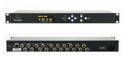
 Orca Technologies, a manufacturer of high-precision time and frequency products based in San Clemente, California, announces the release of its System Matrix Switch (SMS-101) unit designed to provide GNSS signal distribution via a sophisticated switch matrix amplifier system.
Orca Technologies, a manufacturer of high-precision time and frequency products based in San Clemente, California, announces the release of its System Matrix Switch (SMS-101) unit designed to provide GNSS signal distribution via a sophisticated switch matrix amplifier system.
The unit consists of four inputs BNCs labeled A, B, C and D that can be routed to the 12 outputs BNC’s labeled OUT1 through OUT12. Each of the 12 outputs has a dedicated 1 of 4 selector/switch that is used to determine the signal source (A, B, C D) for the output amplifier. Control of the switch is operating mode dependent.
The instrument is designed with 50 Ω (or 100 K) source impedance and will provide unity gain from input to output. There is a control on each of the A, B, C and D inputs to provide a gain of ½ (for operation without 50 Ω termination).
The System Matrix Switch includes comprehensive input signal frequency monitoring logic where the user can define what the expected frequency should be on each input. If the input signal does not fall within the defined margin of error and the unit is in any of the auto modes, a frequency fault condition may cause a switch to occur. The unit also has 4 fault logic level inputs that map to the A, B, C and D inputs. These inputs can be connected to upstream equipment (reference source) to signal the System Matrix Switch that the reference is not viable.
The front panel consists of a four line by 20 character alpha-numeric display, a control keypad and four multi-color input status LEDs. The tactile front panel switches consist of four arrow navigation, SETUP, BACK and FAULT CLEAR keys. The display is an OLED type that provides improved readability over standard LCD displays.
The rear panel contains 12 output signal BNCs, four input signal BNCs, four external fault input BNCs, RJ-45 network connector, USB and power input connector. Each of the four inputs has an activity status LED that indicates the signal applied to the input is valid. This is helpful when hooking up signal cables in the back of an equipment rack to determine that the input has activity.
Other system features include:
• Time Code/Pulse Rate/RF Signal Distribution
• High Level of Flexibility and Configurability
• Configurable from Front Panel or Network Port
• Front Panel LCD, Setup/Control Pushbuttons, Status LEDs
• Rear Panel Status LEDs
• Front Panel LCD/LED Alarm, Audible Alarm, Network Port Alarm
• Web Page Interface for Easy Setup, Control and Status
• Dual Power Supply Option (DC and standard AC).


