 Figures and Tables
In satellite navigation, the user receiver finds its position by measuring its distance to satellites and knowledge of the satellite position. The distance is measured by ranging, i.e., finding the delay of the signal from the transmitter to the receiver. The delay will comprise of payload hardware delay and the geometric range delay. Hence, the payload delay of the signal from generation to radiation is very important and needs to be transmitted in navigation data.
In satellite navigation, the user receiver finds its position by measuring its distance to satellites and knowledge of the satellite position. The distance is measured by ranging, i.e., finding the delay of the signal from the transmitter to the receiver. The delay will comprise of payload hardware delay and the geometric range delay. Hence, the payload delay of the signal from generation to radiation is very important and needs to be transmitted in navigation data.
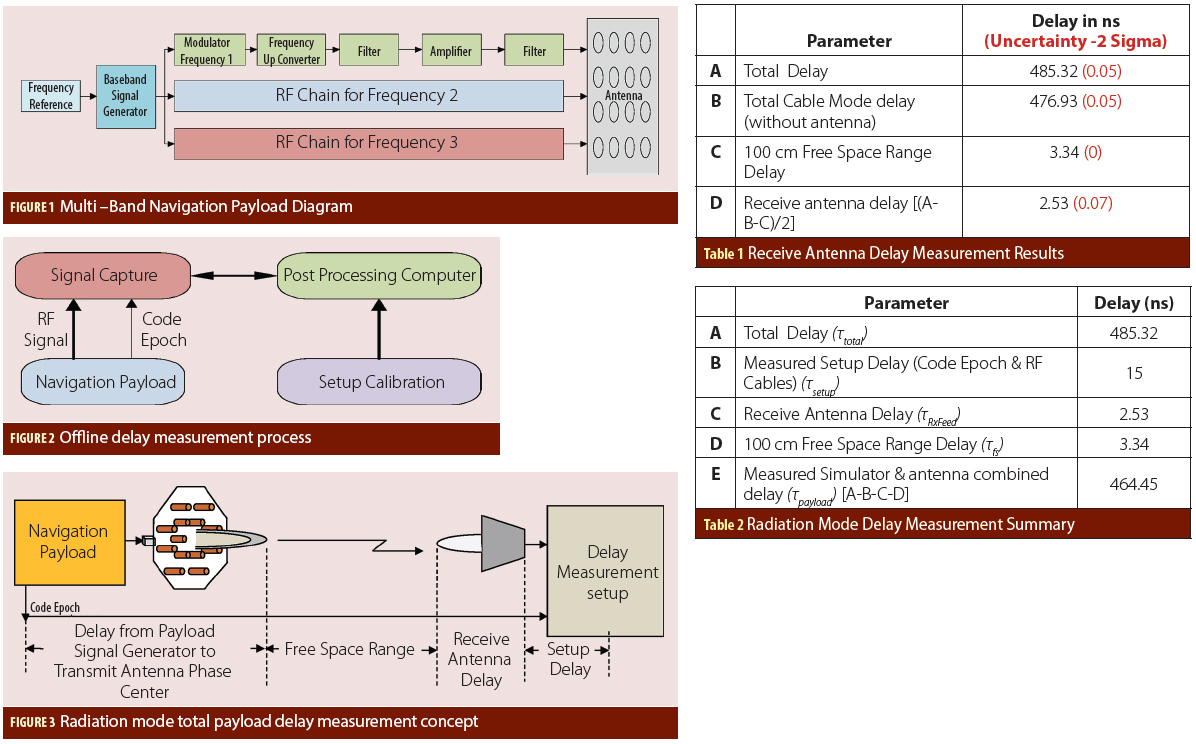
Figure 1 (see inset photo, above right, for figures and tables) presents a typical navigation payload diagram for multiple frequency signal transmission. Corrections for the bias components of the group delay differential are provided to the user segment in the navigation message using parameters designated as (TGD) and inter-signal delay correction (ISC) as described in the Indian Regional Navigation Satellite System Standard Positioning Service Signal in Space Interface Control Document (IRNSS SPS SIS ICD). User receivers employ these parameters to calculate a position and timing solution.
The navigation signals transmitted on each carrier frequency are imperfectly synchronized due to the different hardware paths corresponding to each signal. Each satellite’s navigation message contains parameters describing the timing bias. A GNSS receiver uses these parameters to compute the clock correction for each observation.
Dual-frequency receivers directly employ such corrections as explained in the article by A. Tetewsky et alia listed in the Additional Resources section near the end of this article. However, a single- frequency receiver has to use the computed offset, which must be adjusted to account for the differential group delay between the principal signal and another frequency signal. These delays, known as TGD, result from hardware differences in the onboard signal paths and will vary between satellites.
Channel Delay Parameters
Three different delay parameters arise in a satellite payload: fixed/bias group delay, differential group delay, and group delay uncertainty in bias and differential values as explained in the article by P. Majithiya et alia (Additional Resources). The fixed delay or hardware group delay is a bias term included in clock correction parameters transmitted in the navigation data and is therefore accounted for in the user computation of system time.
This fixed group delay is the time taken for the signal to travel from the common clock through the baseband signal generator, modulator, up-converter, transmitter, and filter to emerge from the satellite antenna. The group delay uncertainty shows the variability in the path delay due to operational environment and other factors. The effective uncertainty of the group delay is typically less than three nanoseconds.
Differential group delay is the delay difference between two different navigation signals. It consists of random plus bias components. The mean differential is defined as the bias component and will be either positive or negative. For a given navigation payload redundancy configuration, the absolute value of the mean differential delay should not exceed a few nanoseconds. The random variation about the mean is typically less than three nanoseconds.
Corrections for the bias components of the group delay differential are transmitted in the navigation message as TGD and ISCs. The measurement inaccuracy and variation in the total end-to-end delay of the payload up to the antenna phase center will directly affect the pseudorange accuracy and ultimately user equivalent range error (UERE).
Navigation Payload Absolute Delay Measurement
The total navigation payload delay can be measured in two ways: addition of integrated payload (without antenna) delay and estimated antenna delay, and total payload (including antenna) delay in radiation mode.
The first method involves two steps. In first,the integrated payload (without antenna) delay is measured. In the second step, the antenna delay is estimated analytically. However, errors in estimation may arise due to variety of reasons. The integrated payload delay measurement technique is described in the following section and is based on details given in the article by P. Patidar et alia (Additional Resources).
Integrated Payload Delay Measurement. The fundamental operation in navigation signal processing is the correlation. The received navigation signal is correlated with a reference code, and the location of the correlation peak provides the estimate of signal delay. A typical navigation receiver does this for many satellites over multiple correlating channels and tracks them in real time to provide continuous positioning. It gets timing reference from the time stamped navigation signal from satellites.
The same principle of correlation is used for delay measurement, although in non–real time. In the offline delay measurement, the RF signal is digitized and recorded in memory. This stored signal can be processed immediately after reception or later. Hence, it is non–real-time or near–real-time operation.
To obtain a measurement of the absolute delay, laboratory equipment representing the satellite payload is connected directly to a measurement test setup. The payload is usually driven by an atomic frequency standard (AFS). The measurement setup is driven by a separate AFS with one order of magnitude better performance. Because highly stable atomic frequency standards are used, no signal dynamics are involved and continuous signal tracking is not required. Figure 2 shows a schematic of the offline delay measurement setup.
The following subsections explain the three main elements of this measurement technique.
Signal Capture. A signal digitizer and recorder digitizes the RF signal from the payload and stores it in memory. The record duration should be at least one code period. Direct RF sampling at very high sampling frequency (10Gsps/40Gsps) is employed to get better resolution and accuracy. A high-speed digital phosphor oscilloscope is used for this purpose.
A computer runs a software routine in MATLAB that commands and acquires data from the oscilloscope. Data recording is triggered by the code epoch from the signal generator unit. Of the payload, which marks the beginning of the codes.
Post Processing. The captured signal in the oscilloscope is transferred through an Ethernet link to the computer for processing. We sampled the recorded signal directly at RF, which needs to be downconverted to baseband before correlation. In the post-processing software, which is implemented in MATLAB, the captured signal is down-converted and filtered prior to correlation.
A reference signal is generated based on the same pseudorandom noise (PN) codes that were used in the payload signal generator. The baseband recorded signal and reference signals are correlated in the frequency domain using Fast Fourier Transform (FFT). The frequency domain version of recorded and reference signals are multiplied and an inverse FFT operation provides the time domain correlation function.
The time domain correlation function is subjected to an acquisition test in order to eliminate false peak detection, after which the peak magnitude and index of correlation function are determined. The index of the correlation peak provides the delay in the samples, which is converted to a time delay by multiplication of the sample duration. To obtain a raw delay measurement, this estimated delay is adjusted for the software processing delay due to filtering involved in the algorithm.
Setup Calibration. Additional digital and RF cables are used in establishing the measurement setup. The code epoch generated in payload signal generator is transported to the digitizing oscilloscope using a digital interface such as a low-voltage differential signaling (LVDS) cable. This cable actually delays recording of signals in the oscilloscope. Hence, its delay has to be added in raw delay values.
Similarly, many additional RF elements such as cables, couplers, attenuators, splitters, and so on are incorporated into the RF path before the oscilloscope digitizes the signal. These RF elements provide additional delay to navigation signals. Therefore, their delay has to be subtracted from raw delay values. The RF elements are also calibrated by means of the previously mentioned offline delay measurement technique, using stimulus from a standard source. (commercial signal generator). The raw delay values are adjusted for digital and RF calibration to determine the absolute hardware delay.
This measurement technique was validated by measuring the delay of calibrated cables. RF cables with calibrated delays of 1, 2, 5, and 10 nanoseconds were compared with offline delay measurements and achieved an accuracy of 0.1 nanosecond. The accuracy is one order better than the typical payload delay–uncertainty specification (three nanoseconds).
The repeatability of this measurement has been verified by various measurement setups involving the mating and demating of cables. The measurements were repeatable within the measurement uncertainty (0.05 nanosecond, 2-sigma). Our proposed method does not need to implement a specific early-minus-late tracking loop in the navigation receiver, as there are no signal dynamics involved in the laboratory test. Hence, the results obtained here are independent of any tracking loop implementation by the receiver.
Antenna Hardware Delay Measurement/Estimation. Most GNSS satellites have helix array antennas with a common shared aperture for transmission of multi-frequency signals. The antenna will have different hardware for different frequency signals. In conventional methods, the antenna delay is measured for different frequency signals by estimating the path length of signal input to the reference surface and from the reference surface to the phase center of the antenna. This kind of delay estimation is based on calculation/analysis and may not represent the actual performance of antenna hardware.
Both the measurement steps (integrated payload measurement and antenna delay measurement) will have a separate measurement setup comprised of many RF and digital elements. Measurement carried out at each step will have its associated errors.
Furthermore, the test setup has to be calibrated and at every step residual calibration errors will be generated due to setup limitation and human errors. These measurement and calibration errors will accumulate at each step and result in an overall delay uncertainty. To avoid this error accumulation, we propose use of the single-shot measurement procedure described in the next section.
Total Navigation Payload Delay in Radiation Mode
We subjected the integrated spacecraft — along with all the antennas — to a radiation mode test. During this test the total payload delay can be measured as per the test setup shown in Figure 3. The payload-generated navigation signal of a particular frequency band is radiated from the respective phase center of a transmit antenna. The spacecraft is mounted at the estimated phase center of that particular signal.
The range from point of transmission to the point of reception is well defined. The signal travels fixed distance in the free space and received by the antenna at its phase center. The received signal is given to offline delay measurement setup. The total measured delay can be expressed as:
τtotal = τpayload + τfs + τRxAnt + τsetup
The total measured delay (τtotal) consists of payload delay (τpayload), free space delay (τfs) between transmit antenna phase center to receive antenna phase center, receive antenna delay (τRxAnt) and measurement setup delay (τsetup). The free space range and receive antenna delay are calibrated values available beforehand.
The measurement setup delay is measured using the procedure mentioned in previous section. After applying all delay values/test results in the preceding equation we can determine the absolute payload delay from ranging signal generation up to the antenna phase center for each frequency and navigation signal.
The delay measurement procedure can be repeated for different antenna off-axis angles. This will give the payload delay variation pattern over the antenna off-axis boresite angle. The antenna phase center variation can be derived from the measured delay pattern.
Experiment Results
An experiment was carried out to validate proposed total payload delay measurement technique in radiation mode. The experimental test setup is shown in Figure 4 (see photo at the top of this article). It consists of a navigation signal simulator (representing the navigation payload) operating in S-band at 2492.028 MHz, a transmit patch antenna, an identical receive patch antenna, and the delay measurement setup described earlier.
The simulator with transmit antenna serves as the analog to a navigation payload. The phase centers of the receive and transmit (both are identical) antennas are known to be on the surface of these antennas.
The simulator output was connected to the transmit antenna. Transmit and receive antennas are kept at a 100-centimeter distance (i.e., the distance between transmit antenna phase center to the receive antenna phase center). The receive antenna output is connected to the delay measurement setup. The total delay in radiation mode was measured as 485.32 nanoseconds.
The measured total delay in the radiation mode will consist of payload delay (i.e., simulator + transmit antenna), free-space range delay, receive antenna delay, and measurement setup delay. Range and measurement setup delays are known whereas the receive antenna delay is unknown.
In this setup, two identical S-band patch antennas are used to transmit and receive signals. The identical antennas will have the same delay. To measure the antenna delay, the delay measurement was repeated in cable mode, i.e., connecting the payload output directly to the delay measurement setup using a bullet adaptor (without antenna). The delay of this adaptor is negligible.
The difference in the delay in radiation mode from that of the delay in cable mode consists of two antenna delays and a range delay. The common delays, including epoch cable delay, will be eliminated in differencing. The receive antenna delay can be easily calculated as shown in Table 1. Table 2 provides a sum-mary of radiation-mode payload delay measurement results. The accuracy of this measurement is 0.1 nanosecond.
Conclusion
The proposed technique measures the total payload hardware delay up to the antenna phase center in a single-shot measurement. The correctness of the final measured delay was cross checked by directly measuring the chip transition delay on a modulated signal at L-band with respect to the code epoch using a high-resolution oscilloscope.
This will eliminate the errors accumulated due to multiple measurements and calibration cycles. It will also avoid the analytical estimation of the antenna delay. ISRO will use the delay measurements obtained in radiation mode to derive payload hardware delay parameters that are broadcasted in the navigation message to correct the satellite clock offsets. The improved measurement accuracy of this delay will, in turn, result in improved position and timing accuracy to the users.
Moreover, the proposed technique can be applied to measure the antenna delay variation pattern over off-axis bore-site angles. The antenna phase center variation can be derived from the measured delay pattern.
Acknowledgements
The authors are grateful to Shri. Tapan Misra, Director, Space Applications Centre (SAC), Ahmedabad and Shri D K Das, Deputy Director, SATCOM & Navigation Payload Area, SAC, for providing overall guidance and encouragement to carry out this work. Authors also would like to thank the SAC antenna team.
Additional Resources
[1] Indian Space Research Organization, “Indian Regional Navigation Satellite System Standard Positioning Service Signal in Space Interface Control Document (IRNSS SPS SIS ICD),” Version 1.0, June 2014
[2] Majithiya, P., and K. Khatri, and J. K. Hota, “IRNSS System: Correction Parameters for Timing Group Delays,” Inside GNSS, January/February 2011
[3] Patidar, P., and D. Upadhyay and P. Majithiya, “Absolute Hardware Delay Measurement of Navigation Payloads,” ASI-SBN Conference 2013, Bangalore, India
[4] Tetewsky, A., and J. Ross, A. Soltz, N. Vaughn, J. Anszperger, C. O’Brien, D. Graham, D. Craig, and J. Lozow, “Making Sense of Inter-Signal Corrections: Accounting for GPS Satellite Calibration Parameters in Legacy and Modernized Ionosphere Corrections Algorithms,” Inside GNSS, July/August, 2009


