 Tables 1 – 4
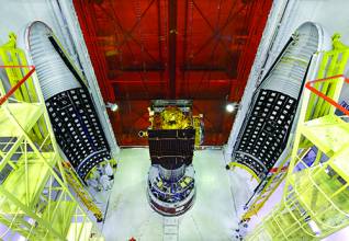
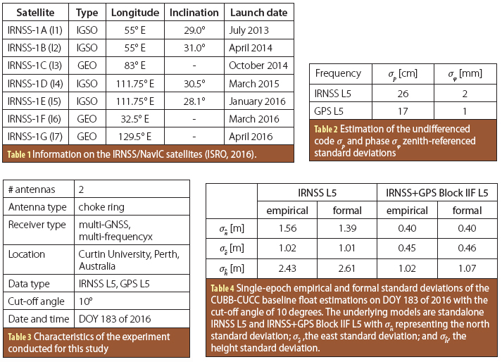
The Indian Regional Navigation Satellite System (IRNSS) became fully operational in May 2016 with the operational name of NavIC (Navigation with Indian Constellation). The system consists of three geostationary orbit (GEO) satellites and four inclined geosynchronous orbit (IGSO) satellites (see Table 1, inset photo, above right). IRNSS has been developed by the Indian Space Research Organization (ISRO) with the objective of offering positioning, navigation and timing (PNT) to the users in its service area. The IRNSS satellites transmit navigation signals on frequency L5 (1176.45 MHz) which is shared by three other GNSSs, i.e., GPS, Galileo and the Quasi-Zenith Satellite System (QZSS), making the IRNSS interoperable with those systems.
All the satellites belonging to the latest generation of GPS, called Block IIF, have been sending out the L5 signal since 2010 as part of the GPS modernization.
With the launch of the last satellite of Block IIF on February 2016, it now has all its 12 satellites operational. The next generation of GPS satellites, GPS III, will also transmit the L5 signal. GPS III is planned to become fully operational with a constellation of 32 satellites by 2025, and the first launch thereof is now expected in spring of 2018.
In this article, we provide the very first empirical and formal L5 ambiguity resolution and corresponding positioning results of the fully operational IRNSS as a standalone system and also in combination with the fully operational GPS Block IIF. For several onshore locations within the IRNSS service area (Figure 1), we investigated the potential of single-frequency (L5) single-epoch real-time kinematic (RTK) positioning. This is carried out for different underlying models, including standalone IRNSS, IRNSS+GPS Block IIF, standalone GPS III and IRNSS+GPS III. With the emergence of low-cost single-frequency RTK receivers and their mass-market applications, our analysis is done for geodetic survey-grade receivers as well as low-cost receivers.
Measurement Experiment
We based our analyses on the IRNSS L5 and GPS L5 data-set recorded by two GNSS receivers of a short baseline between the receiver pair (CUBBCUCC) at Curtin University, Perth, Australia. Figure 2 shows the observed carrier-to-noise densities (C/N0) of IRNSS and GPS L5-signal.
As the GPS L5 signal has larger C/N0 values compared to the IRNSS L5, its precision is expected to be higher with respect to the IRNSS L5. The estimated code and phase standard deviations given in Table 2 (inset photo, above right) confirm this. We used the broadcast ephemeris for both constellations. Table 3 (inset photo, above right) provides further details on the data-set that we used.
Positioning and Ambiguity Resolution Analysis: Empirical and Formal
Here, we concentrate on the L5 positioning performance for both single-system IRNSS and dual-system IRNSS+GPS Block IIF. The data forming the basis of our analysis are one Hertz–sampled on DOY 183 of 2016. Table 4 (inset photo, above right) lists the single-epoch formal and empirical standard deviations of the CUBB-CUCC baseline components.
These results assume that the DD ambiguities are not yet fixed to their integer values, thus being called float solutions. Therefore, we obtained them by using the less precise code observations since the phase measurements are fully reserved for the DD ambiguities. Integrating IRNSS L5 with GPS L5 observations, the baseline estimation precision improves by three to four times horizontally and 2.5 times vertically.
Upon fixing the DD ambiguities, the very precise phase observations take the leading role in baseline estimation. The improvement of the ambiguity-resolved estimations, known as fixed solutions, with respect to their float counterparts, is a factor of 130 in case of standalone IRNSS and 150 in case of IRNSS+GPS Block IIF.
Figure 3 depicts the single-epoch one-second horizontal scatter plot (a) and height time series (b) of the CUBB-CUCC baseline float solutions (in gray), correctly fixed solutions (in green) and wrongly fixed solutions (in red) on the basis of L5 observables of IRNSS+GPS Block IIF collected on DOY 183 of 2016 with the cut-off angle of 10 degrees. The non-ellipsoidal shape of the scatter plot is due to the significant changes that the receiver-satellite geometry experiences during the 24-hour period. The panel (b) also contains the 95 percent formal confidence interval based on the float height standard deviation of which the signature is in good agreement with that of the height error time series, confirming the consistency between data and model.
The occurrence of incorrect ambiguity fixing can be explained by the easy-to-compute scalar diagnostic ADOP (ambiguity dilution of precision) introduced in the article by P. J. G. Teunissen (1997) and referenced in the Additional Resources section near the end of this article. It is defined as the square root of the determinant of the ambiguity variance matrix raised to the power of one over the ambiguity dimension. As a rule of thumb, an ADOP smaller than about 0.12 cycle corresponds to an ambiguity success rate larger than 99.9 percent, as introduced in the article by D. Odijk and P.J. G. Teunissen, (2008) (see Additional Resources). The panel (c) of Figure 3 depicts the time series of the single-epoch ADOP corresponding with IRNSS+GPS Block IIF L5.
Comparing the time series of the ambiguity-fixed height solution with that of the ADOP, the incorrect ambiguity fixing happens during the periods when ADOPs are larger than the value of 0.12 cycle. During some periods such as UTC [03:00- 05:00], although the float height solution shows large fluctuations, the DD ambiguities can still be correctly fixed. Therefore, while a receiver-satellite geometry can be poor for positioning, it can still be strong enough for ambiguity resolution.
As our measure to assess the integer ambiguity resolution performance, we made use of the ambiguity resolution success rate, known as the probability of correct integer estimation described in the article by P. J. G. Teunissen (1998). The 24-hour average single-epoch formal and empirical success rates were in good agreement with each other, confirming the consistency between model and data. The results also showed that upon integrating IRNSS with GPS Block IIF, the single-epoch integer ambiguity resolution success rate improves dramatically from about Ps =15% to Ps = 94%.
Ambiguity Resolution Performance for a Kinematic IRNSS User
The demonstrated consistency between our formal results and their empirical counterparts indicates that the easy-to-compute formal values can indeed predict the expected ambiguity-resolution performance. Here, we turn our focus from a single-epoch scenario to a multi-epoch scenario and conduct a formal analysis of the required number of epochs to fix the DD ambiguities with the success rate of Ps =99.9%. In that regard, we consider several onshore locations over the IRNSS primary and secondary service area (see Figure 4).
Remaining constant over time (in case of no loss-of-lock or cycle slip), the ambiguity resolution performance can improve if this time-constancy is exploited through a kalman filter. For both geodetic survey-grade receivers and low-cost receivers, we compute a 24-hour time series of the number of epochs needed to fix the DD ambiguities with Ps = 99.9% for a kinematic user in the framework of different underlying models. In order to show the statistical properties of these time series schematically, we make use of the boxplot concept introduced in the article by John W. Tukey (1997) referenced in the Additional Resources section near the end of this article. Our boxplot results are based on a 30-second sampling rate.
Geodetic Survey-Grade Receiver Results. Results presented in this subsection are on the basis of four underlying models, i.e., standalone IRNSS, IRNSS+GPS Block IIF, (fully-operational) standalone GPS III, and IRNSS+GPS III. We did not consider the case of standalone GPS Block IIF as this constellation contains only 12 satellites, thus having sometimes fewer than four satellites visible at different locations within the IRNSS service area.
For the geodetic survey-grade receiver, the zenith-referenced code standard deviation that we use for the GPS L5-signal is σpG = 20 cm — as introduced in an article by Nandakumaran Nadarajah et alia (2015) (Additional Resources) — and for IRNSS L5-signal is σpI = 30 cm, which is considered less precise than the GPS L5-signal (see Figure 2). The phase standard deviation for both systems is taken as σφG = σφI = 2mm.
Figure 5 shows the boxplots of the number of epochs to fix the ambiguities with Ps = 99.9%. Each panel contains, from left to right, the results of kinematic standalone IRNSS, IRNSS+GPS Block IIF and standalone GPS III, which are abbreviated in the legend to I, I+GIIF and GIII, respectively. Note that the results of the IRNSS+GPS III are not illustrated as this scenario always provides users within the IRNSS service area with the instantaneous ambiguity resolution with Ps = 99.9%, hence, the single-epoch RTK positioning. Also we did not show the standalone IRNSS results when the 75th percentile is larger than 50 epochs.
In order for our boxplots to be more readable, we used two vertical axes with different ranges in each panel. The boxplots to the left of the shown gray line should be read according to the left axis, and those to the right of the gray line should be read according to the right axis. From Figure 5, the following conclusions can be made:
- Regarding the standalone IRNSS, as one goes further away from the central location (φ=0°; λ=83°), the ambiguity resolution performance gets poorer. Excluding the locations within (0°< φ <20°; 65°< λ <101°), the standalone IRNSS user needs a considerably long time to fix the DD ambiguities with Ps = 99.9%.
- Integration of the IRNSS with the GPS Block IIF brings a huge benefit to the users within the IRNSS service area, especially for those on the border of the secondary service area. Nearly instantaneous ambiguity resolution and RTK positioning is feasible during the whole day for those locations within (0°< φ <20°; 65°< λ <101°).
- As to the standalone GPS III performance, one can see that on average fewer than 10 epochs are needed to fix the DD ambiguities with Ps = 99.9%.
- Given Ps = 99.9%, IRNSS+GPS III always provides the users within the IRNSS service area with the instantaneous ambiguity resolution and, hence, single-epoch RTK positioning.
Low-Cost Receiver Results. Thus far, with Ps =99.9%, we have shown that the ambiguity resolution can be carried out almost instantaneously when using GPS III L5, and instantaneously when using IRNSS+GPS III L5. Now, we will assess the ambiguity resolution performance of these two underlying models when using low-cost single-frequency receivers. For such receivers, the zenith-referenced observation standard deviations are taken as σpI = 100 cm, σpG = 75 cm and σφG = σφI = 3 mm.
Figure 6 shows the boxplots of the number of epochs needed to fix the ambiguities with Ps = 99.9%, for GPS III L5 (Left) and IRNSS+GPS III L5 (Right), which are abbreviated in the legend to GIII and I+GIII, respectively. From this figure, one can conclude:
- For the single-system GPS III, on average fewer than 20 epochs are required to fix the DD ambiguities.
- Integrating GPS III with IRNSS, almost instantaneous (less than five epochs) ambiguity resolution becomes feasible at all the locations within the IRNSS service area. Therefore, almost instantaneous RTK positioning would become possible.
Summary and Conclusion
For the fully operational IRNSS as a standalone system and also in combination with GPS, we have provided a first assessment of L5 integer ambiguity resolution and positioning performance. Following an empirical analysis and showing the consistency between data and model, we performed a formal analysis of the number of epochs needed to successfully fix the DD ambiguities for a kinematic user within the IRNSS service area for both geodetic survey–grade and low-cost single-frequency receivers.
Given a geodetic survey-grade receiver, the standalone IRNSS user needs quite a long time to fix the DD ambiguities. Meanwhile, the IRNSS+GPS Block IIF as well as the standalone GPS III user can carry out almost instantaneous RTK positioning during the whole day for most of the locations within the IRNSS primary service area. With such a high-grade receiver, single-epoch RTK becomes feasible provided that IRNSS is integrated with GPS III. Switching from geodetic survey-grade to low-cost receivers, this integration can still provide almost instantaneous RTK positioning at all the locations within the IRNSS service area.
Additional Resources
[1] Bensky, A., Wireless Positioning Technologies and Applications, Artech House, 2016
[2] GPS Directorate, Navstar GPS Space Segment/ User Segment L5 Interface Specification (IS-GPS- 705B), 2011
[3] GPS World, “First GPS III Satellite Completes Critical Test,” available online here, published January 19, 2016, accessed August 9, 2016
[4] Indian Space Research Organization, Indian Regional Navigation Satellite System: Signal in Space ICD for Standard Positioning Service, Version 1.0, ISRO Satellite Centre, June 2014
[5] Indian Space Research Organization, PSLV-C33/IRNSS-1G, available here, published April 2016; accessed June 1, 2016
[6] Lockheed Martin, “Lockheed Martin Powers on the First GPS III Satellite,” available here, published February 28, 2013; accessed 9 August 2016
[7] Marquis W., and M. Shaw (2016), "GPS III: Bringing New Capabilities to the Global Community,” September/October 2011, Inside GNSS, pp. 34–48, accessed August 9, 2016.
[8] Nadarajah N., and A. Khodabandeh, P. J. G. Teunissen PJG, “Assessing the IRNSS L5-Signal in Combination with GPS, Galileo, and QZSS L5/E5asignals for Positioning and Navigation,” GPS Solutions 20(2):289–297, 2015
[9] Odijk, D., and P. J. G. Teunissen, “ADOP in Closed Form for a Hierarchy of Multi-Frequency Single-Baseline GNSS Models,” Journal of Geodesy 82(8):473–492, 2008
[10] Teunissen, P. J. G., (1997), “A Canonical Theory for Short GPS Baselines. Part I: The Baseline Precision. Journal of Geodesy 71(6):320–336
[11] Teunissen, P. J. G., (1998), “Success Probability of Integer GPS Ambiguity Rounding and Bootstrapping,” Journal of Geodesy 72(10):606–612
[12] Tukey, J. W., Explanatory Data Analysis, vol 1, Reading, Mass: Addison-Wesley Publishing Co., 1977


