 Figures 1-6
Real-time position accuracy, achievable in dense urban areas using low-cost equipment, is currently limited to tens of meters. If this could be improved to five meters or better, a host of potential applications would benefit. These include situation awareness of emergency, security and military personnel and vehicles; emergency caller location, mobile mapping, tracking vulnerable people and valuable assets, intelligent mobility, location-based services and charging, augmented reality; and enforcement of curfews, restraining orders and other court orders.
Real-time position accuracy, achievable in dense urban areas using low-cost equipment, is currently limited to tens of meters. If this could be improved to five meters or better, a host of potential applications would benefit. These include situation awareness of emergency, security and military personnel and vehicles; emergency caller location, mobile mapping, tracking vulnerable people and valuable assets, intelligent mobility, location-based services and charging, augmented reality; and enforcement of curfews, restraining orders and other court orders.
A further accuracy improvement to around two meters would enable navigation for the visually impaired, lane-level road positioning for intelligent transportation systems, aerial surveillance for law enforcement, emergency management, building management, newsgathering, and advanced rail signaling.
This article explores how 3D mapping can be used to achieve a “step change” in real-time GNSS performance in dense population centers, including urban canyons.
The Problem
Buildings and other structures block many GNSS signals in urban environments. When obstructions block satellite signals that cross the street at right angles, allowing only along-street signals to reach a receiver, signal geometry and positioning accuracy decline. In extreme cases, where the ratio of the building heights to the street width is very high, the number of directly received signals may be insufficient to compute a position solution.
Another well-known signal propagation effect occurs when buildings, walls, vehicles, and the ground reflect GNSS signals. Metal, metallized glass, and wet surfaces are particularly strong reflectors. Where the direct line-of-sight (LOS) signal is blocked and only a reflected, or non-line-of-sight (NLOS), signal is received, a ranging error occurs that is equal to the additional path taken by the NLOS signal.
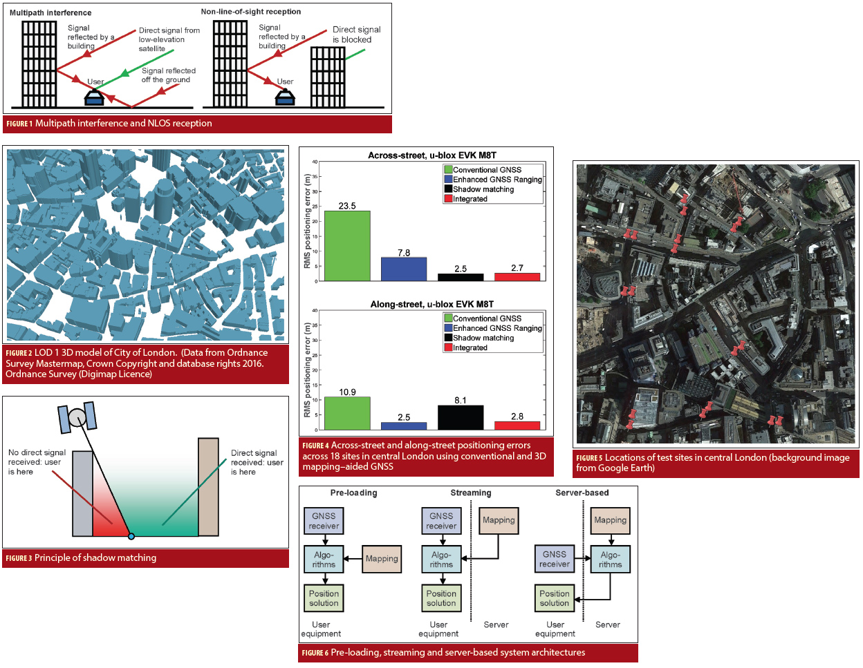
Strong NLOS signals can be difficult to distinguish from direct LOS signals, particularly using a smartphone, which has a linearly polarized antenna. Reflected signals can interfere with reception of the direct LOS signals, a phenomenon known as multipath interference or more simply, multipath, because the signal is received via multiple paths. Figure 1 (see inset photo, above right, for all figures) illustrates both phenomena.
GNSS user equipment can minimize ranging errors due to multipath interference by exploiting receiver signal processing technology at the expense of increased power consumption and hardware cost. However, this approach does not mitigate NLOS reception errors at all.
Multi-constellation receivers have significantly improved the availability of GNSS positioning in dense urban areas. However, accuracy remains a problem. In hostile signal propagation environments such as dense urban areas, the stand-alone, single-epoch positioning accuracy of GNSS is degraded to an average of about 25 meters. In the worst cases, position errors can exceed 100 meters.
Filtered or carrier-smoothed positioning algorithms can perform better, but these require an accurate position solution for initialization. They then need a sufficient number of good-quality GNSS signals to maintain solution accuracy and, hence, the ability to reject poor measurements using innovation filtering. In practice, this can be difficult to achieve in challenging urban environments.
Outdoor Wi-Fi positioning is accurate to around 25 meters, while other radio positioning techniques either offer poorer accuracy or require expensive dedicated infrastructure. Dead-reckoning techniques, including wheel-rotation sensing and pedestrian dead-reckoning using step detection, require accurate initialization, and their position accuracy then decreases as distance measurement errors accumulate.
If we are to achieve low-cost, real-time accuracy of five meters or better in challenging urban environments, a whole new approach is needed. Currently, 3D mapping–aided GNSS presents a great opportunity.
The Opportunity
To implement 3D mapping–aided GNSS, we need three things: measurements, mapping, and algorithms. In dense urban areas, the more satellites that are available for use, the better. Therefore, the return of GLONASS to full operational capability in 2011, followed by the wide availability of GLONASS-capable receivers presented a step-change in signal availability. In 2016, with the Galileo satellite deployment well under way and the extension of BeiDou from a regional to a global system, we are in the midst of a second step-change.
To implement advanced positioning algorithms, we need access to the “raw” measurement data, namely, the pseudorange and signal-to-noise ratio (SNR) or carrier-power-to-noise-density ratio (C/N0). Pseudorange rate (Doppler) and carrier phase can also be useful. Survey receivers have always provided this information, but obtaining these data from consumer receivers has historically been problematic. Today, however, some low-cost GNSS receivers generate pseudorange and SNR measurements from all GNSS constellations, providing access to this data through the application programming interface (API) on smartphones and tablets running the Android Nougat operating system that have a compatible GNSS chipset.
The second ingredient, 3D mapping, can prove expensive when it comes to highly detailed 3D city models. However, simple block models, known as level-of-detail (LOD) 1, are sufficient for most 3D mapping–aided GNSS implementations. (Figure 2 shows an example.). The free, editable OpenStreetMap provides building maps for major cities worldwide, much of it three-dimensional (This can be viewed online using, for example, the F4 Map demo, noting that a default height is assumed for 2D buildings.)
Data is available from national mapping agencies with various terms and conditions, and private commercial companies such as Google and Apple also hold large amounts of 3D mapping data. Although such digital map coverage is far from universal, it tends to be available in dense urban areas where it is most needed. Conventional stand-alone GNSS positioning works well enough in low-density areas.
The final ingredient is advanced positioning algorithms that take advantage of 3D mapping. Many algorithms have been developed. Some use pseudoranges while others use SNR measurements with varying trade-offs between performance and processing load. Over the past five years, results have been published from more than 10 different research groups spread across Europe, North America, Japan, and the Middle East.
What Can Be Done?
3D mapping can be used to provide three types of information for aiding GNSS positioning. The first, and simplest, is the terrain height. Next are the predictions of which satellites will be directly visible at a given position and time, i.e., which lines of sight are blocked by buildings and which are not.
Finally, 3D mapping can be used to predict signal reflections, including the path delay of the reflected signal with respect to the direct signal and, potentially, its relative amplitude. However, amplitude is difficult to predict because 3D mapping data doesn’t include information on building reflectivity at GNSS frequencies, which can be quite different from optical reflectivity.
Terrain height-aiding is useful because, by constraining the position solution to a surface, it effectively removes a dimension from the positioning problem. In open areas, terrain height-aiding only improves the vertical position solution (as one might expect). However, in dense urban areas where the signal geometry is poor, it can improve the horizontal accuracy by almost a factor of two.
We can use satellite visibility predictions to aid both conventional ranging-based GNSS positioning and a new class of SNR-based positioning algorithms known as shadow matching. Each GNSS signal is predicted to be directly visible in some areas and blocked (shadowed) in other areas.
Shadow matching assumes that the user is in one of the directly visible areas if the received SNR is high and in one of the shadowed areas if the SNR is low or the signal is not received at all. Figure 3 illustrates the general principle. Repeating this calculation for each GNSS signal enables one to reduce the area within which the user may be found.
In practice, the SNR distributions of direct LOS and NLOS signals can overlap, particularly when using a smartphone antenna. Furthermore, real urban environments and signal propagation behavior are more complex than can be represented using 3D mapping. Therefore, a practical shadow-matching algorithm works by scoring a grid of candidate positions according to the degree of correspondence between the satellite visibility predictions and the SNR measurements. This enables inaccuracies in the process to be treated as noise so that a correct position is still obtained provided there is sufficient “signal.”
Due to the building geometry, shadow matching is normally more accurate in the cross-street direction than the along-street direction, which complements ranging-based GNSS positioning in dense urban areas. Shadow matching enables users to determine which side of the street they are on in environments where other positioning technologies do not.
Satellite visibility predictions can be used to aid ranging-based positioning in a number of different ways. Where the position is already known to within a few meters, we can predict which signals are NLOS with reasonable accuracy and simply exclude them from the position solution (assuming there are sufficient direct LOS signals). Otherwise, which signals are directly visible depends on the actual position of the user. A simple approach is to determine the proportion of candidate positions at which each signal is predicted to be directly visible. This information is used to weight each measurement within the position solution and to aid consistency checking. This approach typically improves the positioning accuracy by 20–25 percent and can handle initialization errors of about 100 meters.
To make the best use of satellite visibility prediction, a conventional least-squares (or extended Kalman filter) positioning algorithm should be replaced by an algorithm that scores candidate position hypotheses, according to the difference between the measured and predicted pseudoranges (assuming LOS propagation). Different assumptions about the error distribution can then be made at various candidate positions — according to which signals are predicted to be LOS or NLOS at each position. Thus a symmetric error distribution can be assumed for LOS signals and an asymmetric distribution for NLOS signals, with the scoring adjusted accordingly.
The candidate positions may be distributed in a regular grid or semi-randomly (as in a particle filter). Terrain height-aiding is used to associate a height with each horizontal coordinate, enabling the search space to be limited to two dimensions. University College London (UCL) has combined this hypothesis-scoring ranging algorithm with shadow matching, which has reduced the root mean square (RMS) horizontal positioning error in dense urban areas from 26 meters to 3.9 meters using data from a consumer-grade GNSS receiver — a sixfold improvement. Figure 4 shows the across-street and along-street positioning errors obtained at 18 sites in central London, depicted in Figure 5.
3D mapping can also be used to predict reflected signals. For shadow matching, this potentially provides more information from which to predict the SNR measurements. For ranging, this can be used to predict which direct LOS signals are subject to multipath interference, enabling us to adjust their weighting or assumed error distribution within the positioning algorithm.
Where the path delay of the reflected signals is predicted, NLOS reception errors may be corrected, enabling NLOS signals to contribute to an accurate position solution. However, accurate correction of NLOS errors requires an accurate position solution, a “chicken and egg” problem. If we already know the position to within a few meters, alternate computation of the position solution and NLOS corrections may be iterated until they converge. For larger uncertainties, we will need multiple starting positions to ensure convergence. Another approach, known as the “urban trench” method, incorporates the reflecting surfaces within the positioning algorithm. However, this only works where we can determine which surface reflects which signals.
A more powerful approach adds NLOS error prediction to positioning by scoring candidate position hypotheses. NLOS corrections are computed for each candidate position. Both grid-based and particle-based methods have demonstrated positioning accuracies within two meters. However, they are computationally intensive.
These different approaches should not be treated as competitors. SNR-based and pseudorange-based algorithms are clearly complementary. Better performance can be achieved by using both and combining the results. Similarly, a computationally efficient algorithm, operating over a wide search area, can be used to initialize a higher-resolution, computationally intensive algorithm operating over a smaller area.
How Practical Is It?
For 3D mapping–aided GNSS to be practical, the processing load and data storage or transmission load must match the intended applications. The algorithms for determining position will run relatively efficiently on a PC, tablet, or smartphone. However, the algorithms for predicting GNSS signal propagation using 3D mapping are much more computationally intensive. Performing ray-tracing of the of a signal’s path for 20 satellite positions and 1,000 user positions can take several minutes of central processing unit (CPU) time.
This problem has two solutions. The first is pre-computation. For predicting satellite visibility at street level, 3D building boundaries — representing the surfaces and edges of a structure — can be computed for a one-meter grid of candidate positions. Each building boundary comprises the elevation threshold below which satellite signals are blocked for each azimuth. Satellite visibility can therefore be predicted very quickly simply by comparing the satellite elevation with the building boundary elevation at the appropriate azimuth. The main drawback to this approach is that the building boundary data can take up more space than the original 3D mapping.
The building boundary approach can also potentially be extended to predicting whether or not a reflection is received. The path delays of reflected signals could be pre-computed, but this would create a very large amount of data; so, it may not be practical.
The second approach is to use a graphics processing unit (GPU). A GPU is designed for parallel processing, which enables us to consider multiple candidate user positions simultaneously. Using projection, the visibility of 20 satellites over a 100 • 100-meter position grid may be computed in about a second.
To compute the path delays of reflected signals, ray tracing can be run on a GPU, enabling computation of paths from 20 satellites to 100 candidate positions within a second. Operating the GPU on a mobile device increases power consumption because GPUs typically consume about twice the power of CPUs. However, the power consumption of the GNSS receiver chip is also significant. Because of their operating design, GPUs may also speed up the generation of building boundary data.
Distribution of 3D mapping data is another important factor to consider. Three options for distributing these data include pre-loading, streaming, and server-based positioning, as shown in Figure 6. In all cases, a binary data format should be used to minimize the capacity required.
The terrain height data are easiest to handle. A five-meter grid spacing is sufficient, corresponding to 40,000 points-per- square kilometer. Twelve bits is sufficient to describe the relative height of a point within a tile. Four bytes are needed for the height of each tile’s origin with respect to the datum. Thus, about 60 kilobytes are needed to represent a square kilometer of mapped urban terrain; so, one gigabyte of storage could accommodate map data representing about 17,000 square kilometers, Even more can be stored using data compression.
For 3D modeling of a city’s buildings, about 500 bytes might be used to describe a building to LOD 1, and a square kilometer in a dense urban area might typically contain about 1,000 buildings. Thus, about 100 kilobytes per square kilometer is needed; so, one gigabyte of storage could accommodate about 2,000 square kilometers of data, or enough to create 3D maps for about two cities — again, more with compression.
Building boundaries require a lot more data. To achieve a one degree precision, requires about 300 bytes per building boundary. Assuming that about half the space in a city is outdoors (building boundaries are not required for indoor locations), a 100 • 100–meter tile would require 1.5 megabytes of data without compression. So, one gigabyte of storage would only accommodate about 7 square kilometers of data, perhaps 70 square kilometers with compression. Thus, pre-loading may be practical if the 3D mapping is used directly, but is unlikely to be if building boundaries are used. Pre-loading of pre-computed path delays would not be practical.
Moving on to streaming, if 3D mapping is used directly, buildings within a ~300-meter radius of the predicted user position should be downloaded as they could potentially affect signal reception. This download would require about 150 kilobytes of data. For building boundary data, only the search area is needed, which should be no larger than 100 meters by 100 meters, considering only outdoor locations.
Only azimuths corresponding to the current set of GNSS satellites are needed, which reduces the amount of data required to 90 kilobytes without compression. The pre-computed path delays would comprise one value per satellite, per candidate location, requiring about 125 kilobytes for 10-bit values. Third-generation (3G) mobile download speeds are more than 500 kB/s (4 Mbit/s). Therefore, streaming of mapping data is practical, and substantial data buffering could be accommodated to bridge any gaps in communications coverage.
The final option is to calculate the position solution on a remote server. This requires uploading of the GNSS pseudorange and SNR measurements from the mobile device to the server, and then downloading the position solution. This imposes a minimal communications load and could employ current assisted-GNSS (AGNSS) protocols; so, it would be compatible with all current mobile devices. However, it needs continuous communications coverage. A server would almost certainly use pre-computed building boundaries and possibly pre-computed path delays as well, depending on the size of the user base.
UCL’s combined shadow-matching and GNSS-ranging system, which is accurate to about four meters, uses predictions of terrain height and satellite visibility based on the 3D mapping, but not path delay predictions. Consequently, it can operate in real-time with pre-computed building boundary data, or potentially GPU-based projection from a 3D building model. Thus, 3D-mapping-aided GNSS positioning is a practical proposition.
Other research groups have demonstrated higher accuracy (around two meters) using methods that predict NLOS path delay using 3D mapping. These are too computationally intensive to operate in real-time over a large search area on a mobile device. However, they could be used as the final step in a multi-stage positioning process, following on from the UCL algorithms. With further research, further viable approaches are likely to emerge.
The Way Forward
The GNSS research community has demonstrated that 3D mapping–aided GNSS can vastly improve positioning accuracy in dense urban areas and is practical to implement. Current algorithms could be deployed in consumer location-based services right now. This could operate as an enhancement to server-side AGNSS using current interfaces and protocols. A service provider would have to invest in additional hardware to run the positioning algorithms for multiple users simultaneously and store the 3D mapping.
3D mapping–aided GNSS algorithms could also run on a mobile device, potentially within an app, provided the device has a compatible API and GNSS receiver chip. In this case, a service provider would be required to store the 3D mapping data and download it to users on demand. Clearly, either architecture needs a viable business model to fund it. One possible driver is enhancing a mobile navigation app’s user experience to attract more customers.
Many specialist applications — such as navigation for the visually impaired, situation awareness of emergency, security and military personnel and vehicles; emergency caller location; and tracking vulnerable people and valuable assets — could also make use of current 3D mapping–aided GNSS algorithms. With a much smaller user base than consumer applications, much less server infrastructure would be required to get them operational.
The scientific community is another potential early adopter of 3D mapping–aided GNSS. Many research groups use GNSS for tracking experimental subjects or for building maps of things they wish to study, such as pollution or wheelchair accessibility.
As these users post-process their data, they are much easier to support. All they need is some positioning software that they can download plus a set of instructions. They can acquire GNSS receivers, which can log pseudoranges and SNR data, or use smartphones that can access these through the API. They can also use existing OpenStreetMap 3D mapping to select test sites where the data are available.
A lot more can be done to increase the performance of 3D mapping–aided GNSS. This is still a new field and further research will improve the accuracy, reliability, and processing efficiency of these techniques. An integrity framework could also be developed. Therefore, 3D mapping–aided GNSS — potentially integrated with other navigation technologies — could meet the needs of more demanding applications, such as lane-level road positioning and aerial surveillance, as well as better serving consumer, specialist, and scientific users.
3D mapping–aided GNSS could potentially revolutionize positioning in dense urban areas. It’s time to start implementing it.
Acknowledgement
Figures 4 and 5 are provided by Dr. Mounir Adjrad of UCL, whose research is funded by the Engineering and Physical Sciences Research Council (EPSRC) project EP/L018446/1, “Intelligent Positioning in Cities using GNSS and Enhanced 3D Mapping.”
The photos on the opening pages of this article were taken by Dr. Adjrad and former UCL students Nachuan Li and Christelle Mekemlong Lando.
Additional Resources
[1] Adjrad, M., and P. D. Groves, “Intelligent Urban Positioning using Shadow Matching and GNSS Ranging Aided by 3D Mapping,” ION GNSS+ 2016, Portland, Oregon USA, September 2016
[2] Adjrad, M., and P. D. Groves, “Enhancing Conventional GNSS Positioning with 3D Mapping without Accurate Prior Knowledge”, ION GNSS+ 2015, Tampa, Florida USA, September 2015
[3] Bétaille, D., and F. Peyret, M. Ortiz, S. Miquel, and L. Fontenay, “A New Modeling Based on Urban Trenches to Improve GNSS Positioning Quality of Service in Cities,” IEEE Intelligent Transportation Systems Magazine, 5(3), 59-70, 2013
[4] Bourdeau, A., and M. Sahmoudi, “Tight Integration of GNSS and a 3D City Model for Robust Positioning in Urban Canyons,” ION GNSS 2012, Nashville, Tennessee USA, September 2012
[5] Groves, P. D., and Z. Jiang, L. Wang, and M. Ziebart, “Intelligent Urban Positioning using Multi-Constellation GNSS with 3D Mapping and NLOS Signal Detection,” ION GNSS 2012, Nashville, Tennessee USA, September 2012
[6] Groves, P. D., and L. Wang, M. Adjrad and C. Ellul, “GNSS Shadow Matching: The Challenges Ahead,” ION GNSS+ 2015, Tampa, Florida USA, September 2012
[7] Kumar, R., and M. G. Petovello, “Sensitivity Analysis of 3D Building Model-assisted Snapshot Positioning,” ION GNSS+ 2016, Portland, Oregon USA, September 2016
[8] Hsu, L.-T., and Y. Gu and S. Kamijo, “3D Building Model-Based Pedestrian Positioning Method Using GPS/GLOANSS/QZSS and Its Reliability Calculation,” doi 10.1007/s10291-015-0451-7, GPS Solutions, 2015
[9] Isaacs, J. T., and A. T. Irish, F. Quitin, U. Madhow, and J. P. Hespanha, “Bayesian localization and mapping using GNSS SNR measurements,” IEEE/ION PLANS 2014, Monterey, California USA, May 2014
[10] Ng, Y., and G. X. Gao, “Direct Positioning Utilizing Non Line of Sight (NLOS) GPS Signals,” ION GNSS+ 2016, Portland, Oregon USA, September 2016
[11] Obst, M., and S. Bauer and G. Wanielik, “Urban Multipath Detection and mitigation with Dynamic 3D Maps for Reliable Land Vehicle Localization,” IEEE/ION PLANS 2012, Monterey, California USA, May 2012
[12] Suzuki, T., “Integration of GNSS Positioning and 3D Map using Particle Filter,” ION GNSS+ 2016, Portland, Oregon USA, September 2016
[13] Suzuki, T., and N. Kubo, “Correcting GNSS Multipath Errors Using a 3D Surface Model and Particle Filter,” ION GNSS+ 2013, Nashville, Tennessee USA, September 2013
[14] Suzuki, T., and N. Kubo, “GNSS Positioning with Multipath Simulation using 3D Surface Model in Urban Canyon,” ION GNSS 2012, Nashville, Tennessee USA, September 2012
[15] Wang, L., “Investigation of Shadow Matching for GNSS Positioning in Urban Canyons,” Ph.D. Thesis, University College London, 2015. Available here
[16] Wang, L., and P. D. Groves, and M. K. Ziebart, “Smartphone Shadow Matching for Better Cross-street GNSS Positioning in Urban Environments”. 68(3), 411-433, Journal of Navigation, 2015
[17] Wang, L., and P. D. Groves, and M. K. Ziebart, “Urban Positioning on a Smartphone: Real-time Shadow Matching Using GNSS and 3D City Models,” Inside GNSS, Vol. 8, No. 6, pp. 44-56, November/December 2013
[18] Wang, L., and P. D. Groves, and M. K. Ziebart, “GNSS Shadow Matching: Improving Urban Positioning Accuracy Using a 3D City Model with Optimized Visibility Prediction Scoring,” NAVIGATION, 60(3), 195-207, 2013
[19] Yozevitch, R., and B. Ben-Moshe, “A Robust Shadow Matching Algorithm for GNSS Positioning,” NAVIGATION, 62(2), 2015


