This article — Part 1 was published in the September/October 2018 issue — presents the authors’ experience in setting up an airborne pseudolite (UAVlite) with the needed ground-based infrastructure to perform code and phase ranging performance analysis. UAVlites transmit GNSS-like signals free from any local transmitter multipath (in contrast to ground-based transmitters) and can in principle be localized in real-time through a synchronized network of ground stations which may also broadcast the UAVlite positions in real-time. Furthermore, software defined radio allows for the easy broadcast of new navigation signals and testing them in real environments. Here, decimeter code range accuracy and millimeter phase range accuracy has been demonstrated.
As stated in Part 1, there is an increasing importance for GNSS open services for our economy, society, e.g., in the field of traffic monitoring and controlling, as well as for timing applications. Because of this it is necessary to enhance the availibility and more importantly the reliability of GNSS services. In this section of the article, we showcase the results of the performance of the ground system, and a working principle is proven and shown that it is a potential technique in the wide field of signal analyzation and optimization, be it in the field of multipath, channel coding, authentication or robustness against jamming, spoofing, or other interference for existing GNSS signals as well as for developing potential new GNSS signals.
Results
Performance of Ground System
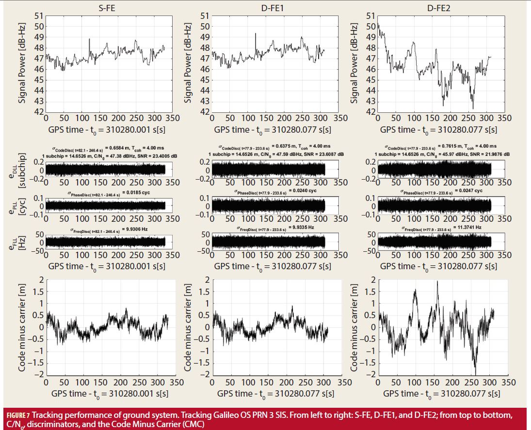
In a first step, the ground system of the testbed is validated. In this step we verify if the working chain of signal receiving, recording, and post processing works and yields reasonable results. Therefore, the Galileo signal in space (SIS) pilot E1C is processed and analyzed and E1B of the SIS is ignored. As in all tests, a sampling rate of 200 MS/s is used and the receiver internal replica signal is a Composite-BOC (CBOC). The tracking results for all three records (from left to right: S-FE, D-FE1, and D-FE2) are plotted in Figure 7. From top to bottom, the C/N0, DLL, PLL, and FLL discriminators, and the Code Minus Carrier (CMC) values are displayed. The tracking performance of the SIS (PRN 3) is satisfying and comes up to expectations. S-FE and D-FE1 are almost identical, because they get their input from the same antenna (Rx1). For the D-FE2 there are slightly different values for C/N0, discriminator, and CMC. This is most likely due to the ~40 meter longer coaxial cable and locally different receiver multipath conditions. This degradation is in the normal range and sufficient for the testbed.
White Rabbit Time Sync Performance within Ground System
In the next step, the FE clock synchronization is evaluated. In the current work, two synchronization approaches are tested. First, as a reference, the comparison of both D-FE inputs is presented. The D-FE has one clock which is used for the sampling of both inputs. Here the best performance is expected as no clock synchronization is needed. Secondly, the clock synchronization with the WR hardware is tested (described earlier). The clock synchronization performance will be measured by comparing the ΔPR Phase and ΔPR Code performance under each synchronization approach. As before, we use the SIS (Galileo OS PRN 3, E1C) for the synchronization performance measurements.
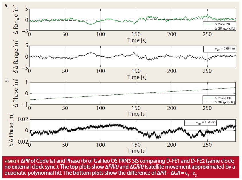
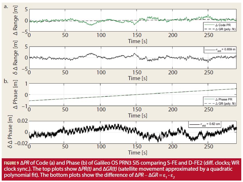
The processing, described in the Concept section, of the code and phase PR of the signals D-FE1 and D-FE2 (same clock; no external clock sync.), is displayed in Figure 7 and yields the ΔPR for code (Figure 8a) and phase (Figure 8b). The top plots of (a) and (b) show ΔPR(t) and ΔGR(t) (the satellite movement was approximated and removed by a quadratic polynomial fit of the ΔPRP). The bottom plots of (a) and (b) show the difference of ΔPR – ΔGR and represent the remaining residual error ε1 – ε2. For the ΔPR code (ΔPRC) a standard deviation of 0.664 meters and for the ΔPR phase (ΔPRP) a standard deviation of 0.58 centimeters is observed. These values are in the expected range of the Galileo OS SIS and prove the basic working principle. In Figure 9 the ΔPRC (a) and the ΔPRP (b) of the signals S-FE and D-FE2 (diff. clocks; WR clock sync.) are presented. The ΔPRC standard deviation is 0.659 meters and the ΔPRP standard deviation is 0.62 centimeters. Comparing the ΔPRP plots of Figure 8 and Figure 9, a clear phase jitter is visible under the usage of the WR synchronization. The 16.6 picoseconds deviation of the WR synchronization yield an estimated range error of approximately 0.5 centimeters. This was calculated by 16.6 ✴ 10-9 ✴ c. This range error is clearly visible in the magnitude of the jitter in Figure 9b. The plots for the ΔPRC in Figure 8a and Figure 9a are almost identical. The values for the standard deviation are equal within the error margin. Therefore it is shown that the WR clock synchronization is sufficient for the code performance evaluation. However, the observed WR clock synchronization deviation of 16.6 picoseconds can become a relevant disturbance for phase processing purposes and needs further investigation, e.g. smoothing of the clock adjustments.
UAV Transmitted Composite-BOC (CBOC) Signal
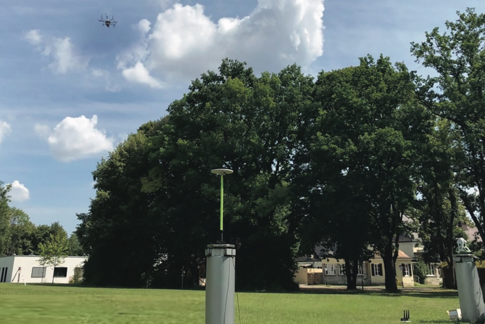
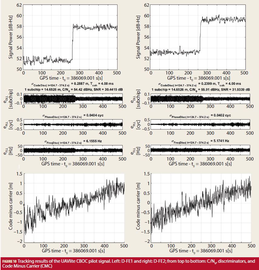
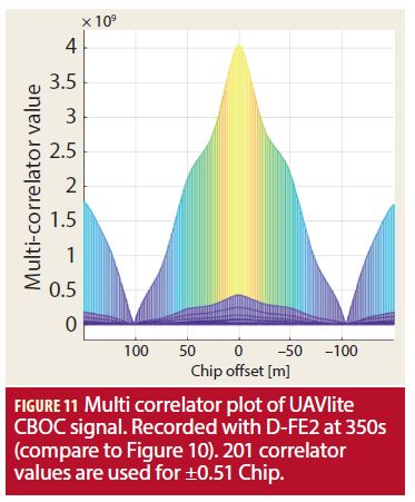
Until now, only the SIS was processed and analyzed to verify that the ground system works as desired. From now on a self-created single CBOC pilot signal is used, with the same parameters as for the Galileo OS E1B CBOC. The transmission sampling rate was 40 MS/s (complex valued). Only the D-FE results will be shown from now on. In the flight test, the drone is hovering between the two Rx antennas at a height of 30 meters, pictured in Figure 1. In Figure 10, the tracking results for the D-FE1 and D-FE2 recording are shown. In the 500-second-long segment the transmitting power was increased by +6 dB at approximately 250 seconds. An increase in code tracking (DLL) and frequency tracking (FLL) performance, by increased power, can easily be seen in Figure 10 (middle row). On the contrary, a slight degradation of the phase tracking (PLL) is visible for the increased power (most likely but still to be verified due to transient errors or oscillator jitter). The CMC variation is in a reasonable range, but the small CMC drift in both signals is an issue for further investigation. As the ground system was tested and this drift only occurs in the UAVlite signal, it is assumed that either temperature or hardware effects are causing this drift in the USRP. A representative multi correlator (MC) plot of the recorded UAVlite signals is presented in Figure 11. The MC plot shows 201 correlation values of the CBOC signal for a chip offset of –0.51 till +0.51 chips.
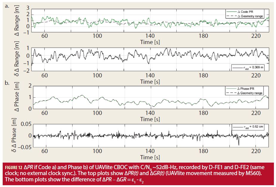
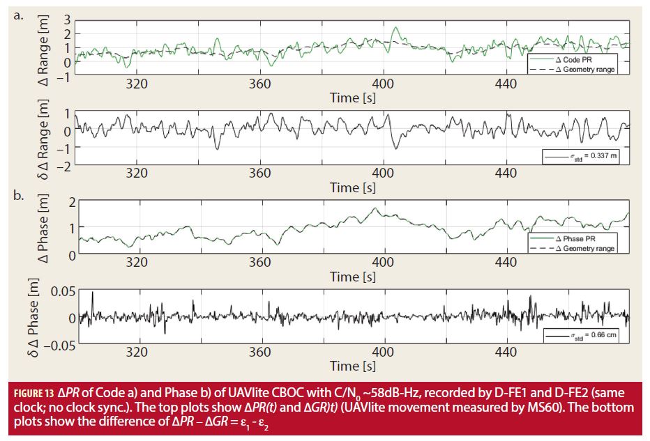
For the ΔPR analysis of the UAVlite signal we analyzed 180 seconds from the lower (50-54 dB-Hz) C/N0 power level and 180 seconds from the higher (57-60 dB-Hz) C/N0 power level. The results for ΔPRC (top) and ΔPRP (bottom) are presented in Figure 12 (lower power) and Figure 13 (higher power). The standard deviation of the ΔPRC with a C/N0≈ 52 dB-Hz is 0.369 meters and with a C/N0 ≈ 58 dB-Hz it is 0.337 meters. Both values are better than for the SIS analysis. This is reasonable as the UAVlite signal was 6 dB stronger. Furthermore it shows that the signal, with 6 dB higher power, has a slightly better ΔPRC standard deviation error. This difference shows the right trend, however, is not significant. But as both signals are strong, no large difference can be expected and the error budget is expected to be dominated by multipath. The standard deviation of the ΔPRP with a C/N0 ≈ 52 dB-Hz is 0.52 cm and with a C/N0 ≈ 58 dB-Hz it is 0.66 cm. As mentioned above, the degradation of the phase tracking in the higher power signal also causes a bigger standard deviation in the ΔPRP.
Summary and Outlook
An innovative concept for code and phase performance analysis in a real test environment was presented with a detailed discussion of all relevant components needed to set up such a system. The ground system was tested and verified with Galileo OS SIS. It is shown that the WR clock synchronization induces a small jitter effect on the phase measurement, which is, however, uncritical in scale for delta pseudorange code performance analysis and is also acceptable in most cases for delta pseudorange phase performance analysis. In the subsequent analysis of the UAVlite transmitted E1B CBOC signal good values for code and phase tracking are reached as well as for the ΔPRC and ΔPRP performance analysis. The values are smaller or in the same range as for the SIS. However it was observed that the transmitting chain of PC, USRP, and Tx antenna seems to induce some effects, which are visible in both a small CMC drift and reduced phase tracking performance for higher transmitting power. These effects and the underlying processes need to be studied in more detail. The working principle is proven and it is shown that it is a potential technique in the wide field of signal analyzation and optimization, be it in the field of multipath, channel coding, authentication or robustness against jamming, spoofing, or other interference for existing GNSS signals as well as for developing potential new GNSS signals. Furthermore, the extension to multiple ground stations to allow real-time UAVlite position determination without multistation is straightforward thanks to the WR synchronization technology.
In the future we want to further improve the testbed and use the infrastructure for testing navigation message authentication (NMA) as well as spreading code authentication (SCA) methods. Furthermore, we want to use the testbed to validate the benefit of the Galileo PRS service compared to the Galileo OS. Testing promising future GNSS signal structures is also in the planning. On a bigger time scale, the expansion to multiple UAVlites and multiple receiving antennas is envisaged.
Manufacturers
The software defined radio reconfigurable device used in the Pseudolite (Transmitter) section is a SDR USRP 2950R from National Instruments, Austin, Texas. Also, the virtual bench with a customized application program that was used to measure the time difference between the clocks of the WR-LENs was the VB-8054 from National Instruments.
In Receiver System where the authors state that the UAVlite signals as well as the signals in space (SIS) are captured, they are done so with two Trimble Zephyr 2 Geodetic antennas from Trimble, Sunnyvale, CA. Also in the Receiver Section, IFEN multi-GNSS software receiver front-ends (FE) from IFEN GmbH, Poing, Germany, are used; the SX3 Dual-RF-FE (D-FE) and the SX3 Single-RF-FE (S-FE).
In Positioning and Range Verification, the authors are referring specifically to the MultiStation MS60 from Leica Geosystems, Heerbrugg, Switzerland.
The GNSS receiver used in the Front-end Clock Synchronization section is the PolaRx4TR from Septentrio, Leuven, Belgium and Torrance, CA.
The drone referenced in the UAV section is the DJI Spreading Wings S1000+ Octocopter from DJI, Shenzhen, China.
Acknowledgments and Disclaimer
Acknowledgement should go to Gerhard Kestel, Stephan Ullrich, and Mathias Philips-Blum for their support during the measurement campaigns and their work setting up the testbed system. The project is self-funded by the Institute of Space Technology and Space Applications of the “Universität der Bundeswehr München.” The setup and the gained knowledge are and will be used for the DLR projects SatNavAuth (FKZ: 50 NA 1703) and NeedForPRS (FKZ: 50 NP 1708).
Authors
Daniel Simon Maier has a professional training as a technical draftsman and received a bachelor in Physics in 2015 and a master in Applied and Engineering Physics in 2017 from the Technical University of Munich (TUM), Germany. Since 2017 he has been a research associate at the Institute of Space Technology and Space Applications of the “Universität der Bundeswehr München.” His current research interests include GNSS signal generation, signal authentication, and signal performance analysis.
Thomas Kraus graduated with a M.Sc. in Electrical Engineering from the University of Darmstadt, Germany. In 2008, he joined the Institute of Space Technology and Space Applications of the “Universität der Bundeswehr München.” He’s been working as a research associate on several projects of the German Space Agency (DLR) and European Space Agency (ESA-ESTEC). His main research focus is on future receiver design offering a superior detection and mitigation capability of intentional and unintentional interferences.
Daniela Elizabeth Sánchez Morales studied Telematics Engineering at Instituto Tecnológico Autónomo de México (ITAM) in Mexico City. She also holds a Masters degree in satellite applications engineering from the Technical University Munich (TUM). She has been a research associate at the Institute of Space Technology and Space Applications (ISTA) since 2017. Her main research area is sensor fusion. Her current research focuses on LiDAR, sensor fusion between LiDAR and GNSS/INS, and relative and absolute navigation algorithms particularly for terrestrial applications.
Ronny Blum received his Masters in Physics from the University of Basel, Switzerland. He then worked at Würth Elektronik in the field of signal transmission and later on at the Forest Research Institute in Freiburg im Breisgau in the field of GNSS reception within the forest. In 2017 he joined the University of Federal Armed Forces Munich, where he is working in the field of GNSS software receiver.
Prof. Thomas Pany is with the Universität der Bundeswehr München at the faculty of aerospace engineering where he teaches satellite navigation. His research includes all aspects of navigation ranging from deep space navigation to new algorithms and assembly code optimization. Currently he focuses on GNSS signal processing for Galileo second generation, GNSS receiver design, and GNSS/INS/LiDAR/camera fusion. To support this activities, he is developing a modular GNSS test bed for advanced navigation research. Previously he worked for IFEN GmbH and IGASPIN GmbH and is the architect of the ipexSR and SX3 software receiver. He has around 200 publications including patents and one monography.
Em. Univ.-Prof. Dr.-Ing. habil. Dr. h.c. Guenter W. Hein is Professor Emeritus of Excellence at the University FAF Munich. He was ESA Head of EGNOS & GNSS Evolution Programme Dept. between 2008 and 2014, in charge of development of the 2nd generation of EGNOS and Galileo. Prof. Hein is still organising the ESA/JRC International Summerschool on GNSS. He is the founder of the annual Munich Satellite Navigation Summit. Prof. Hein has more than 300 scientific and technical papers published, carried out more than 200 research projects and educated more than 70 Ph. D.´s. He received 2002 the prestigious Johannes Kepler Award for “sustained and significant contributions to satellite navigation” of the US Institute of Navigation, the highest worldwide award in navigation given only to one individual each year. G. Hein became 2011 a Fellow of the US ION. The Technical University of Prague honoured his achievements in satellite navigation with a Doctor honoris causa in Jan. 2013. He is a member of the Executive Board of Munich Aerospace since 2016.


