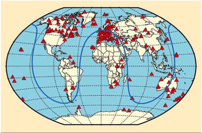
 FIGURE 1: Geographical overview of the 170 IGS stations tracking SVN62/PRN25 during its current 90-day checkout period. The blue curve illustrates the ground track of the spacecraft on August 9, 2010.
For the complete story, including figures, graphs, and images, please download the PDF of the article, above.
On May 27, 2010, the U.S. Air Force successfully launched the first satellite of the Block II “follow-on” (Block IIF) series, the fourth generation of GPS spacecraft that features more precise and powerful signals, an extended design life, and several other technical advances.
Space vehicle IIF-1, also referred to as SVN62/PRN25, has been injected into the orbital plane B, slot 2 position of the GPS constellation and is expected to be set healthy for navigation uses by the end of August.
Since the activation of the L-band transmitter on June 6, a set of around 170 globally distributed ground stations of the International GNSS Service (IGS) equipped with “all-in-view” receivers (which are capable of tracking both healthy and unhealthy satellites) have been collecting dual-frequency L1/L2 pseudorange and carrier phase measurement data from SVN62/PRN25 (Figure 1, see inset, above).
To relate the measurements consistently to the satellite’s center of mass, the phase center characteristics of the transmitting antenna on board the spacecraft must be precisely known. Because GPS satellites usually exhibit different (block- as well as satellite-specific) antenna phase center characteristics, the IGS community is now faced with the question of how to deal with the relevant antenna phase center parameters for the new Block IIF spacecraft.
Whereas “official” values for the phase center offsets (PCOs) have recently been published by the satellite’s manufacturer, hardly anything is known about possible direction-dependent variations (PCVs) of the antenna phase center location. This prompted us to make a first attempt to estimate the satellite’s antenna PCOs and PCVs based on the first weeks of IGS data (available online here). In the course of the PCO determination, we also studied the yaw-attitude behavior of the new Block IIF-1 spacecraft during the recent eclipse season of orbital plane B.
This article relates the initial analyses and results of those studies.
Spacecraft-Fixed Reference System
To gain a clear understanding of the satellite antenna phase center and attitude issue, let us first introduce a spacecraft-fixed reference system. The origin of this system coincides with the satellite’s center of mass.
The y-axis points along the nominal rotation axis of the solar panels, the z-axis points along the navigation antenna boresight toward the center of the Earth, and the x-axis pointing toward the hemisphere containing the Sun completes the right-hand system. The azimuth under which a tracking station is seen from the satellite is chosen to count clockwise from the y-axis toward the x-axis when looking in the direction of the negative z-axis.
. . .
Satellite Antenna Phase Center Characteristics
The L-band navigation antenna array on board a GPS spacecraft is designed to illuminate the Earth hemisphere with nearly constant signal strength. It consists of 12 single helical elements arranged in two concentric rings on the Earth-facing satellite panel. Where the inner-ring is composed of four equally spaced elements that produce a broader beam with high signal power, the outer-ring contains eight elements that produce a narrow beam with a weaker signal.
. . .
GPS IIF-1: A Bad Attitude?
The best knowledge about the satellite antenna phase center characteristics is useless in the end, if the spacecraft’s orientation, also referred to as its attitude, with respect to the inertial reference system is wrong.
Satellite antenna phase center correction models accounting for “horizontal” PCOs and PCVs strongly depend on the azimuth of the particular tracking station on the ground. The precise calculation of the azimuth, however, requires an exact knowledge of the satellite’s yaw angle at each point in time. The yaw angle is the angle between the spacecraft-fixed x-axis and the direction of the spacecraft velocity (“along-track”) vector.
To get an insight into the yaw-attitude laws of the GPS Block IIF-1 spacecraft during eclipse season, we studied the evolution of the horizontal satellite antenna PCO estimates in the vicinity of orbit noon and orbit midnight using a technique that we refer to as “reverse kinematic point positioning.”
In this approach, we keep all relevant global geodetic parameters fixed and estimate the satellite clock and antenna phase center positions epoch-by-epoch using the 30-second observation and clock data from the IGS ground station network. The estimated horizontal antenna PCOs implicitly provide the instantaneous state of the spacecraft’s yaw-attitude.
We found that the Block IIF-1 satellite, when passing through the Earth’s shadow, behaves to a certain extent like a Block IIR vehicle. That means that the satellite is basically able to keep its nominal yaw-attitude even in the absence of sunlight.
. . .
Conclusions
This article reports on the phase center characteristics of the transmitting antenna on board the first GPS Block IIF satellite. The L1/L2 pseudorange and carrier phase observables of about 170 IGS sites have been analyzed in order to derive the satellite’s antenna PCOs and PCVs.
We found that the estimated horizontal PCOs are in excellent agreement with those provided by the satellite’s manufacturer. The estimated PCVs differ significantly from those of the other GPS satellite blocks and show the typical fourfold pattern with variations in an order of magnitude that cannot be ignored in high-precision GPS applications.
PCO/PCV analyses involving the L5 carrier phase are still pending. They will become possible as soon as an adequate set of globally distributed stations exists that are equipped with L5-capable receivers and L5-calibrated geodetic antennas.
In its second part, the article gives a first insight into the yaw-attitude behavior of the new spacecraft during the recent eclipse season. We have demonstrated that the presence of the horizontal antenna phase center eccentricity in combination with the significant azimuth-dependent PCVs requires a proper model for the satellite’s noon-turn and the midnight-turn maneuvers.
Future studies are needed to assess whether the results actually represent the final operational attitude control or just reflect initial in-orbit tests done by the U.S. Air Force operators.
For the complete story, including figures, graphs, and images, please download the PDF of the article, above.
Acknowledgments
The author gratefully acknowledges IGS for providing global GPS data and ephemerides.
Additional Resources
[1] Dilssner, F. , and T. Springer, C. Flohrer, and J. Dow, “Estimation of phase center corrections for GLONASS-M satellite antennas”, Journal of Geodesy, Volume 84, Issue 8, Page 467-480, 2010


