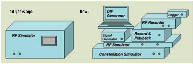
 FIGURE 1: GNSS multi-channel signal simulator 10 years ago on its own (left) and with its ever-growing family (right)
For the complete story, including figures, graphs, and images, please download the PDF of the article, above.
In this article we describe the design and operation of a generic GNSS RF simulator. We also will look at the main types of GNSS RF simulators, their designs and specifics, their advantages and disadvantages.
Product designers, manufacturers, and systems integrators have used simulators for decades now for various purposes. We use them for testing, R&D, and education. In the previous article in this series (Inside GNSS, July/August 2010), we looked at the simulator as a tool needed at every stage of receiver development from R&D to a production, certification, and maintenance.
A Growing Family
Simulator technology is now a mature one with sophisticated algorithms and designs behind it. For a long time many users only needed to see simulators as “black boxes,” supplying them with GNSS signals “out of the box.” The time has come, however, for all users to be able look inside of a simulator and understand its design, specification, functions, and limitations, because all of these devices provide a different set of capabilities, often constrained by their design.
Recently, new devices with functionality similar to that of simulators have appeared, expanding the simulator’s family. These include digitized intermediate frequency (DIF) generators, constellation simulators, signal recorders, record and playback systems, and more. How can we best use all these devices?
As the simulator family expands (Figure 1, see inset, above), users need to understand those devices more than ever in order to ensure quality of the solutions for which the equipment is employed.
As we might expect, particular simulator devices better fit a particular task than others. In this article we look at various designs of some members of the simulator family and discuss how a simulator design may affect its specification and functionality.
Let’s start off with probably the most familiar category: GNSS signal simulators. Full-scale RF signal simulators have had their functionality shifted to a digital domain, which provides a more flexible and economic solution. This type is generally divided into two groups, single-channel and multi-channel simulators.
Single-Channel Simulator
A single-channel simulator — sometimes also known as a signal generator — is usually capable of simulating a signal from one satellite with extended control over various parameters.
In particular, such a simulator can usually control a signal’s Doppler profile. This function is very handy when it comes to tuning up receiver tracking loops. Simulators of this type are widely used for production and R&D tests.
A single-channel simulator can be designed in pretty much the same way as a satellite transmitter. We illustrate all designs in this article using GPS L1 simulation as an example.
. . .
Pseudolite
A single-channel simulator can be used as a pseudolite. Such a simulator should implement RTCM pulsing and a frequency offset to confront a “near-far” problem and reduce potential effects on non-participant receivers. Pulsing is a pulse-wise interruption of the transmitted signal made to decrease the value of receiving signal power for non-participant receivers.
. . .
Multi-Channel Simulator
A simulator from the second type within the RF type has multiple channels and is also sometimes called a constellation simulator. It provides one with coherent simulation of multiple satellite signals in a defined operating environment. This type of equipment is widely used for R&D work and in almost all design, manufacturing, and post-sales tests.
Three key features define a multi-channel simulator: the capability of recreating GNSS RF signals so as to be indistinguishable from the real signals by a tested receiver; the capability of providing repeatability of the signal generation; and the ability of a user to control most of the simulation environment.
The user should be able to know exactly what parameters have been set for the simulation, which is known as the true model.
. . .
Ionospheric Error: Broadcast and True Models
The distances between a given receiver and the satellites it is tracking are calculated and serve as the basis for creating code and carrier observations for each instance of time. In the real world, however, GNSS signals are delayed and distorted during their propagation through the atmosphere and often obstructed and attenuated by foliage or buildings. There are also other error sources.
. . .
Ionospheric Error: Code Delay and Phase Advance
GNSS ranging errors mainly come from signal propagation through the atmosphere. Ionospheric error is calculated as a delay in code observations and an advance in phase observations. All other errors contribute to code and phase observations with the same sign, only as delays. Most significant errors among these are tropospheric delays and satellite clock errors.
. . .
Additional Ionospheric Error Models: Spatial Correlation
Some R&D tasks may require more specific models to be implemented, especially where it concerns a development of new algorithms.
One example is spatially correlated ionospheric errors. Algorithm development related to virtual reference station (VRS), network RTK, or ionospheric research may require an ability to generate a spatially correlated ionospheric model in which the signal is generated for more than one receiver and ionospheric errors are properly correlated.
. . .
Additional Ionospheric Error Models: Scintillation
Both scintillation and multipath errors are implemented in simulation differently from other errors because they don’t affect code and carrier measurements in the same way as propagation delays. Mutipath errors and scintillation errors are transformed to range errors only after they go through a receiver baseband processor.
. . .
Multipath: an Error That Is Simulated Differently
The multipath error is created in a simulator by duplicating a simulated satellite signal with a phase shift and attenuation in amplitude.
. . .
Simulator of Type I: Analog Simulator
Now we look at the ways in which the signal calculated in equations (3), (4) and (5) is transferred to RF signal. How it works depends on the simulator type.
At first we consider an analog simulator, which was the first type of a simulator to be developed. It was designed in a very similar manner to the way a satellite transmitter is working.
. . .
Simulator of Type II: Digital Simulator
We continue our discussion about creating simulated signals using the other type of simulator family, namely the digital simulator. These have appeared quite recently, within the last decade.
We will concentrate on the digital category because we consider that its underlying technology is superior to the analog type. Moreover, even the satellite transmitters for future and modernized current GNSSes may move to digital signal generation, because it makes the transmitters more flexible and easy to reprogram on-the-fly.
The digital versus analog issue with GNSS simulators is not the same as with cameras. One can argue that an analog camera would provide one with a better quality, although almost everyone uses a digital one nowadays — probably because a digital camera is easy, more flexible, and more modern technologically. Some people make the same argument regarding vinyl records and compact disks — that the analog technology produces a better, truer musical sound quality.
From such examples, one could easily get a wrong impression that analog design is by definition superior to digital. In fact, an analog simulator may provide way less signal quality than a digital one, for reasons both related and unrelated to its analog character.
. . .
Doppler Effect: Is It Really There?
We usually think of a Doppler effect as a physical change in a signal frequency caused by movement of a transmitter relative to receiver (or vice versa) at substantial velocity. In reality, if we just recreate a signal with code and carrier observations for each epoch on the receiver side using equation (2), then we get the correct signal representation without any extra care for explicit changes caused by Doppler effect.
. . .
Simulator Type III: DIF Generator/Record & Playback
We could logically call the third type of simulator a software simulator. However, we prefer to avoid this term in order to escape confusion with other less sophisticated software bearing a similar name that simulates a GNSS receiver’s operation as an output.
. . .
As in case of a simulator, the quality of a signal restored in this way depends on the quality of the front-end hardware. We will look at the quality and constraints of playback devices in detail in the final article of this series.
Simulators: The Dark Side
As with any advanced technological achievement, from the invention of smoking to creation of the Internet, the possibility of misuse and even unlawful use must be faced at some stage.
We look here at two main issues. First of all, we should address a theoretical concern about potential use of simulators as jammers. Luckily, we are not in any danger of that — because it makes no sense from a cost/benefit perspective. Simulators are inherently far more flexible, complex, calibrated, and, consequently, expensive devices than any jammer would need to be. On the contrary, simulators provide a way to research and understand how we can deal with the problem of intentional and unintentional signal interference.
Another potential problem that probably will require regulating at some point is copyright infringement of simulator products — in particular, the selling or distributing of files recorded from simulators.
A recorder/playback device can record and playback a signal from a simulator. One way to confront such unlicensed copying is to embed a watermark into a signal, — the equivalent of a digital signature. Such a watermark, though recorded and retransmitted, cannot be detected by a conventional receiver, in effect, providing a copyright for the products of a simulator.
What’s Next?
In the final article in this series to be published in a forthcoming issue of Inside GNSS, we will look at the specifications of various types of simulators, their parameters, and the ranges, constraints, and importance of these factors for particular tests.
For the complete story, including figures, graphs, and images, please download the PDF of the article, above.
Acknowledgement
The first author would like to thank Dr. Tsujii from JAXA for inspiring cooperation related to ionospheric research and also for making available his analysis of the ReGen simulated scintillation signal for this publication. The first author would also like to thank Graham Ockleston from Rakon Ltd. for his valuable advice.
Additional Resources
[1] Heinrichs, G., and E. Löhnert, E. Wittmann, and Roland Kaniuth, “Opening the GATE Germany’s Galileo Test and Development Environment,” Inside GNSS, May/June 2007, pp. 45–52
[2] Petrovski I., K. Okano, S. Kawaguchi, H. Torimoto, K. Suzuki, M. Toda, and J. Akita, “Indoor Code and Carrier Phase Positioning with Pseudolites and Multiple GPS Repeaters”, Proceedings of the Institute of Navigation ION GPS/GNSS 2003, September 9–12, 2003, Portland, Oregon USA
[3] Pullen S., and G. Opshaug, A. Hansen, T. Walter, P. Enge, and B. Parkinson, “A Preliminary Study of the Effect of Ionospheric Scintillation on WAAS User Availability in Equatorial Regions” Proceedings of ION GPS-98, Institute of Navigation, Alexandria, Virginia, USA, 1998
[4] Tsujii, T., and H. Tomita, Y. Okuno, S. Kogure, M. Kishimoto, K. Okano, D. Manandhar, I. Petrovski, and M. Asako (2007), “Development of a BOC/CA Pseudo QZS and Multipath Analysis Using an Airborne platform”, Proceedings of the Institute of Navigation National Technical Meeting 2007, San Diego, California, USA, January 22–24, 2007, pp 446-451
[5] Tsujii, T., and T. Fujiwara, Y. Suganuma, H. Tomita, and I. Petrovski (2009), “Development of INS-Aided GPS Tracking Loop and Flight Test Evaluation,” 2009 International Symposium on GPS/GNSS, November 4–6, 2009, Jeju, Korea


