As a navigation satellite transmits multiple signals on single frequency (e.g., Open Service and Restricted Service over L5 Band), these are combined on a common carrier to comprise a composite signal. This composite signal passes through navigation payload subsystems such as an up-converter, traveling wave tube amplifier (TWTA), filters, and so on. These subsystems may introduce adverse effects on the signal, such as amplitude and phase distortion, nonlinear effects, gain imbalance, IQ imbalance, and phase noise.
As a navigation satellite transmits multiple signals on single frequency (e.g., Open Service and Restricted Service over L5 Band), these are combined on a common carrier to comprise a composite signal. This composite signal passes through navigation payload subsystems such as an up-converter, traveling wave tube amplifier (TWTA), filters, and so on. These subsystems may introduce adverse effects on the signal, such as amplitude and phase distortion, nonlinear effects, gain imbalance, IQ imbalance, and phase noise.
Such impairments degrade the quality of navigation signals and affect the navigation performance, i.e., the pseudorange. In this article, we propose the use of error vector magnitude (EVM) as a parameter to quantify these adverse effects on the navigation signals. The EVM provides a unified representation of all these transmitter impairments.
A navigation receiver finds its position by calculating satellite-to-receiver pseudoranges using satellite ephemeris and time information available in the navigation message. The accuracy of the navigation solution depends upon the size of various ranging errors caused by such factors as ephemeris error, satellite clock error, ionospheric error, tropospheric error, code tracking error, multipath error, and satellite geometry. Hence, we need to analyze and to identify the effects of payload impairments on the ranging error in order to help determine the performance of a navigation payload.
The code tracking error is a key factor in determining received signal quality, while EVM is a measure of transmitted signal quality. In this article we establish a relationship between EVM and the code tracking error. First, we define and present formulas for EVM and the code tracking error and then derive the relationship between them. Next we describe an experimental setup that uses a precision carrier-to-noise generator and vector spectrum analyzer (VSA) to verify the relationship between EVM and the signal-to-noise ratio (SNR) and present the results of tests using this setup, which show a linearly varying relationship between code tracking error and EVM.
Error Vector Magnitude
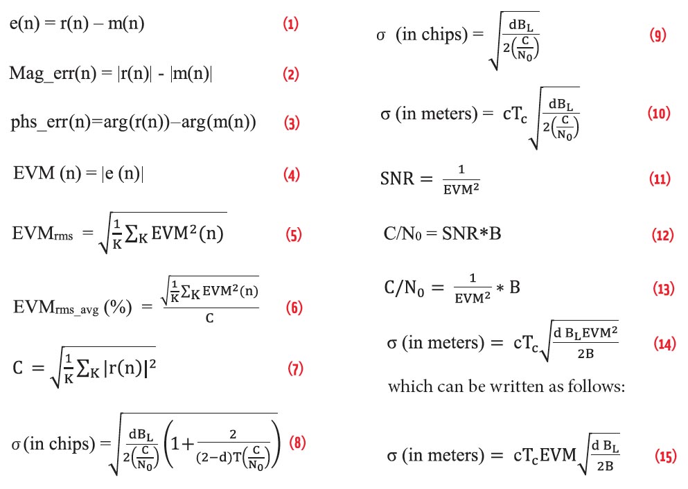
As discussed in the paper by Hassun et alia listed in the Additional Resources section near the end of this article, the error vector is defined as the difference of measurement waveform to the reference waveform. Considering the discrete waveforms, the definition can be given as:
Equation (1) (see inset photo, above right, for all equations)
in which n represents the symbol points; r(n), the reference waveform; m(n), the measured waveform; and e(n), the error vector.
All quantities are complex numbers, representing IQ samples of the respective waveforms. Error vector provides information regarding deviation of the measured waveform from the reference waveform. The following parameters are further defined as:
- Magnitude Error: the magnitude difference between a reference waveform and a measured waveform. If magnitude error is mag_err (n) then,
Equation (2)
- Phase Error: the phase difference between a reference waveform and a measured waveform. If phase error is phs_err(n) then,
Equation (3)
- Error Vector Magnitude (EVM): the magnitude of the error vector. If the error vector magnitude is EVM(n) then,
Equation (4)
EVM represents the combined effects of magnitude error and phase error. Figure 1 shows the relationship of magnitude error and phase error with EVM. The EVM measurement unifies the effects of many subsystems and provides a single representative parameter.
The RMS value of EVM is defined as:
Equation (5)
where K is the number of unique symbols in a constellation.
EVM is usually expressed as a percentage of the signal energy. So, EVMrms is required to be normalized with respect to signal energy as discussed in the article by A. Georgiadis listed in Additional Resources. For a non-constant modulus constellation (such as quadrature amplitude modulation or QAM), EVM can be normalized with respect to maximum or minimum symbol energy. In this case the value of EVM will depend on modulation type. Therefore, it is better to normalize with average signal energy. The normalized EVMrms_avg can be expressed as:
Equation (6)
Here C is the normalization constant given as:
Equation (7)
Code Tracking Error
A navigation receiver obtains the pseudorange measurement by estimating the received code phase in a navigation satellite signal. It employs a code-tracking loop, generally a non-coherent delay lock loop (DLL) to track the signals from each satellite. The DLL correlates the received signal with a slightly early and a slightly late replica of the code.
Error in code phase estimate is introduced in the code-tracking loop due to the presence of noise, interference, and other impairments. This error propagates in the measurement of a pseudorange. The code tracking error (σ) in the presence of white noise is a random variable with zero mean, thus:
Equation (8)
where d = spacing between early-late correlator; BL = Delay Lock Loop Bandwidth; T = integration time of the correlator; and C/N0 = carrier-to-noise density ratio.
In equation (8), the second term 1/T(C/N0), represents the square-law small signal suppression effect of the noise and becomes important if the signal-to-noise ratio is lower. We are considering the SNR at the output of the payload, which will be higher. So, for the higher SNRs equation (8) can be represented as follows:
Equation (9)
The code tracking error (one-sigma) in meters can be obtained as follows [3][4]:
Equation (10)
c (speed of light) ≈ 3 * 108 m/sec and TC = code chip duration.
EVM and Code Tracking Error Relationship
As mentioned earlier, EVM represents the effects of noise and various linear/non linear distortions of the transmitter. These distortions may be correlated or uncorrelated with the desired signal.
Due to de-spreading of the pseudorandom noise (PRN) code, the correlated/colored noise and distortion at the correlator input becomes uncorrelated and normally distributed at output. Even the deterministic DC offset is mapped on a random signal in the code domain. Thus, independent of a particular implementation, a simple additive white Gaussian noise (AWGN) channel between encode and decode can replace a total CDMA transceiver. So, as described in the paper by M. Ali-Hackl et alia (Additional Resources), reception of a signal with a certain EVM is equivalent to reception of a distortion-free signal in AWGN with the following SNR:
Equation (11)
Here we do not consider receiver noise; so, the noise in the SNR is only due to transmitter impairments. The SNR of the spread spectrum signal is a function of the point in the receiver under consideration. Therefore, it is convenient to normalize the SNR to a one-hertz bandwidth and then achieve a signal-to-noise ratio that is bandwidth independent:
Equation (12)
From (11), the C/N0 at the receiver correlator input with pre-correlation bandwidth (B) can be related with EVM as follows:
Equation (13)
Substituting (13) in (10) for C/N0 gives the following code tracking error:
Equation (14)
Equation (15)
Equation (15) gives the desired relation between the code tracking error and EVM.
Verifying the Results
The relationship between EVM and code tracking error derived in the previous section can be verified by measuring σ against EVM. In doing this, we cannot directly control EVM and then measure the code tracking error with standard instruments. With proper assumption of system parameters, however, we can first verify the relation between EVM and SNR and then establish the relation between σ and EVM.
Verification of relation between EVM and SNR. We designed a test setup to verify the relation between EVM and SNR that incorporated a precision C/N generator, a vector spectrum analyzer (VSA), and a vector signal generator as shown in Figure 2. The PSG generates a clean test signal, which is input to the C/N generator. The C/N generator outputs a noisy signal with a controlled C/N ratio. The corresponding EVM is measured on the VSA. Table 1 provides the instrument settings for the test setup, and Figure 3 and Figures 4, 5 and 6 show the C/N generator output constellation and spectrum observed at the VSA for 10- and 20-decibel C/N ratios, respectively.
Table 2 and Figure 7 compare the measured and theoretical EVM as per equation (2). These results verify the EVM versus SNR relationship.
Establishment of relation between σ and EVM. Typical navigation signal parameters and typical user receiver parameters are given in Table 3 and Table 4, respectively.
With these parameters, the relationship between EVM and code tracking errors is established as given in equation (15). Results are given in Table 5 and Figure 8 for navigation signal. In Table 5, the SNR and C/N0 are calculated based on equation (11) and (12), respectively. Here, only satellite transmitter impairments are considered in calculating the code tracking error. Obtained results show that the code tracking error varies linearly with the transmitter EVM.
Typical C/N0 at navigation receiver is ≈45 dBHz and corresponding code tracking error for typical navigation signals is ≈1 m. The transmitter design should be such that it has negligible impact on receiver code tracking error. It should be preferred to have transmitter contribution at least two orders lower than receiver thermal noise. From Table 5, we may conclude that typical navigation transmitter EVM should be better than 10%.
Conclusion
The theoretical SNR versus EVM relation is verified by experiment. It is known that the code tracking error in a navigation receiver is inversely proportional to square root of the C/N0. This article establishes that the code tracking error varies linearly with the transmitter EVM and can be used to evaluate the performance of navigation payloads.
Acknowledgment
The authors are thankful to Shri. A. S. Kirankumar, Director Space Applications Center for his encouragement for this study. The authors are also grateful to Shri. D. K. Das, Shri. Sumitesh Sarkar and Shri. Parimal Majithiya of Space Applications Center for their guidance and encouragement.
Additional Resources
[1] Ali-Hackl, M., and S. Freisleben, R. Heddergott, and W. Xu, “Error Vector Magnitude as a Figure of Merit for CDMA Receiver Design,” Siemens AG, Information & Communication Mobile, Munich Germany EPCOS AG, Surface Acoustic Wave Device, Munich Germany, European Wireless, 2004
[2] Braasch, M. S., and A. J. Van Dierendonck, GPS Receiver Architectures and Measurements, September 2009
[3] Georgiadis, A., “Gain, Phase Imbalance, and Phase Noise Effects on Error Vector Magnitude,” IEEE Transactions on Vehicular Technology, Vol. 53, No. 2, March 2004
[4] Hassun, R., and M. Flaherty, R. Matreci, and M. Taylor, “Effective Evaluation of Link Quality Using Error Vector Magnitude Techniques,” IEEE Wireless Commincation Conference, 1997
[5] Misra, P., Global Positioning System Signals, Measurements and Performance, Gangajamuna Publication, 2006
[6] Parkinson, B. W., and J. J. Spilker Jr., Global Positioning System: Theory and Application, volume 1


