 EQUATIONS 1 -11
GLONASS currently uses a frequency division multiple access (FDMA) technique to distinguish the signals coming from different satellites in the Russian GNSS constellation. The GLONASS L1 and L2 bands are divided into 14 sub-bands, and each satellite transmits in one of these.
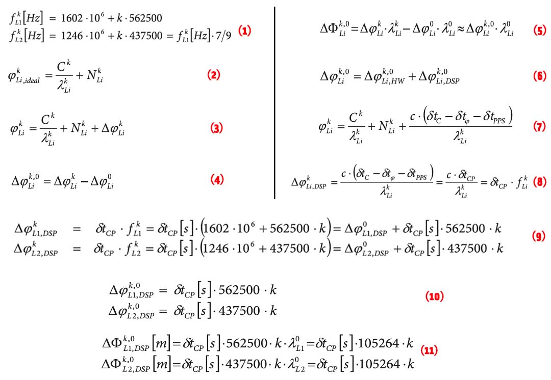
The sub-bands are identified by frequency numbers k, from -7 to 6. The GLONASS L1 and L2 carrier frequencies, in hertz, at a frequency number k are defined by:
GLONASS currently uses a frequency division multiple access (FDMA) technique to distinguish the signals coming from different satellites in the Russian GNSS constellation. The GLONASS L1 and L2 bands are divided into 14 sub-bands, and each satellite transmits in one of these.
The sub-bands are identified by frequency numbers k, from -7 to 6. The GLONASS L1 and L2 carrier frequencies, in hertz, at a frequency number k are defined by:
Equation 1 (see all equations, inset, above right)
Use of the FDMA technique has long been known to cause significant inter-frequency biases in carrier phase measurements of GLONASS satellites. As already postulated in early GLONASS developments, these biases can be well modeled as a linear function of the frequency number k, and are very similar on L1 and L2 when expressed in units of length. (See, for example, the article by A. Povalyaev listed in the Additional Resources section near the end of this article.)
As reflected by the articles by L. Wanninger cited in Additional Resources, these biases have also been shown to tend to be the same for all receivers of a given brand, but significantly different across brands. The fact that the biases depend on the GLONASS frequency number and are not the same between brands significantly complicates the real-time kinematic (RTK) ambiguity resolution process in heterogeneous base/rover combinations.
Although the general properties of the GLONASS inter-frequency carrier phase biases (linearity with respect to k, homogeneity within a given brand, and equality between the L1 and L2 bands) are well known and documented, the origin of these biases in the receiver signal processing chain remains largely unexplained. The widely accepted hypothesis is that the biases originate in the analog hardware and thus are difficult to tackle without specialized laboratory equipment.
This article provides new insights into this question. Our analysis demonstrates that the major cause of inter-frequency carrier phase biases is not to be found in the analog RF part of the receiver, but rather in the way the measurements are generated in the digital part of the receiver.
This discovery opens new perspectives and new hope for the calibration of the biases between receivers. Our discussion here will show that the biases can be compensated to millimeter-level in an absolute sense.
Inter-Frequency Carrier Phase Biases: A Definition
Most existing research on inter-frequency carrier phase biases in GLONASS has concerned itself with differential biases in the form of single and double differences, which reflects the form in which the biases appear in differential positioning algorithms, such as RTK. Instead, this paper addresses the source of biases inside a single GNSS receiver, and for that purpose it is more convenient to concentrate on non-differenced observations and non-differenced biases.
To focus on the inter-frequency phase biases, we shall purposely ignore in our formulas all other error sources such as atmospheric delays, multipath, or tracking noise. We also ignore inter-frequency code biases, which shall not be discussed in this article.
Under this idealized assumption, the code and carrier phase measurement generated in a GNSS receiver differs only by an integer number of wavelengths:
Equation 2
Where φkLi is the phase measurement, in units of cycles, for the frequency band Li (i=1 or 2) for a GLONASS satellite transmitting in a frequency channel k. Ck is the code measurement, NkLi is an integer phase ambiguity, and λkLi is the carrier wavelength, defined as λkLi = c/ƒkLi with c being the speed of light and ƒkLi defined by Equation (1).
In this article, we will use the symbol “φ” for phase measurements expressed in cycles and “Ф” for phase measurements expressed in meters. To convert φ to Ф, it is sufficient to multiply it by the carrier wavelength λkLi.
Equation (2) represents an ideal non-biased case. If biases affect carrier phase measurements, Equation (2) must be rewritten as:
Equation 3
where ΔφkLi is the carrier phase bias term, in cycles. This term is dependent on the frequency number, hence the superscript k.
The GLONASS inter-frequency carrier phase bias is commonly defined as the difference of the bias at frequency number k with respect to the bias at frequency number 0. In this article, we will denote the inter-frequency carrier phase bias as Δφk,0Li when expressed in units of cycles, and ΔФk,0Li when expressed in units of length:
Equation 4
and
Equation 5
The approximation in Equation (5) is accurate to a sub-millimeter level and hence is valid in all practical cases. Figure 1 shows the L1 and L2 GLONASS inter-frequency carrier phase bias ΔФk,0Li and ΔФk,0L2 as a function of the frequency number k for a line of a dual-frequency, multi-GNSS receivers that we used in our research discussed here.
The biases shown in Figure 1 are computed from the results in the 2012 article by L. Wanninger (Additional Resources) and, as stated by that author, are defined relative to a set of receivers taken as reference. Figure 1 illustrates that the inter-frequency biases are linear functions of the frequency number, and, when expressed in units of length, are equal for L1 and L2.
According to Wanninger’s research, GLONASS inter-frequency phase biases for a given brand can be characterized by a single parameter: the slope of their linear dependence upon the frequency number expressed in centimeters per frequency number. In the case of the dual-frequency, multi-GNSS receiver that we used, the biases of which are shown in Figure 1, the slope is 4.9 centimeters per frequency number and is the same on L1 and L2. The value of the slope for other receiver manufacturers can be found in L. Wanninger (2012).
In the next section it will be shown that inter-frequency carrier phase biases generated in GNSS receivers consist of two components: biases caused by analog radio-frequency hardware and biases caused by the digital signal processing (DSP):
Equation 6
Although analog hardware is commonly assumed to be a main source of biases, we will show that this is not the case: in reality, the digital signal processing is by far the dominant source of biases.
Inter-Frequency Biases Generated by Analog Filters
GNSS signals are well known to undergo a group delay and a phase shift when passing through the analog components of the antenna and the receiver. This effect is frequency-dependent and, hence, is not the same for the various GLONASS frequency channels.
The phase response of an analog filter characterizes the phase shift introduced by the filter as a function of the carrier frequency. The phase response for a particular receiver can be computed a priori if the filter design is known, or it can be accurately measured in an absolute sense using specialized laboratory equipment such as a network analyzer.
As an example, Figure 2 shows the phase response across the GLONASS L2 band for the L2 analog filter of the dual-frequency, multi-GNSS receiver, the bias of which is shown in Figure 1. In this figure, the effect of the frequency-independent delay introduced by the filter has been removed.
From this figure, we can see that the phase shift variation caused by that RF filter is very small (sub-millimeter level) and cannot account for the decimeter-level biases shown in Figure 1.
More generally, the observed properties of the inter-frequency carrier phase biases clearly do not correspond to what would be caused by analog filters because of the following:
- analog filters would not systematically cause the same bias on L1 and L2
- analog filters would not systematically produce linear biases, and
- analog biases are sensitive to temperature, while no temperature effect has been observed thus far, according to Wanninger’s research.
Inter-Frequency Biases Generated in the DSP Chain
In GLONASS RTK processing, common practice uses code measurements to estimate the difference between the clock biases of the rover and base receivers, with the assumption that the same differential clock bias applies to carrier phases. An incorrect estimation of the differential clock bias is known to introduce carrier phase residual errors when fixing GLONASS ambiguities (See the article by D. Kozlov et alia cited in Additional Resources).
It is not commonly known, however, that the fundamental assumption that code and carrier phase measurements share the same clock bias is generally incorrect. There exist at least two mechanisms by which the measurement generation algorithm in the receiver’s digital signal processing (DSP) can induce a difference in code and carrier clock bias.
First, DSP techniques commonly adjust code measurements by some constant offset, for instance, to compensate for group delay effects in the reception chain, in order to align the time at which the pulse-per-second (PPS) strobe is generated. This adjustment is done in the receiver firmware by adding a constant term c · δtPPS to all raw code measurements. This adjustment, being constant for all satellites, is seen as a code clock bias by the positioning algorithm. If it is applied to code measurement only, it obviously introduces a difference between code and phase clock biases.
The second cause of code-phase bias is found in the correlation process that takes place in the digital hardware. Signal tracking involves maximizing the correlation between the incoming signal and local signal replicas generated by code and carrier generators implemented in the receiver’s digital circuits. This process is illustrated in Figure 3.
A delay δtC exists from the code generator to the correlator, and another delay δtφ from the carrier generator to the correlator. These delays are fixed for a given receiver architecture and do not vary with temperature. Typically, they are multiples of the sampling interval used by a particular receiver design.
Depending on the chip architecture, the delays δtC and δtφ are not necessarily equal. This is important, because any difference between these delays is directly reflected in a bias between the code and carrier phase measurements.
With the delays δtPPS, δtC, and δtφ, Equation (2) does not hold any more and must be rewritten as follows:
Equation 7
The third term in the right-hand side of Equation (7) is the DSP-induced carrier phase bias defined in Equation (3):
Equation 8
where δtCP = δtC – δtφ – δtPPS is the aggregate code-phase bias (CPB) induced by the digital processing, in units of time.
Using the values of ƒkLi defined in the equations in (1), we can rewrite the DSP-induced L1 and L2 phase biases as follows:
Equation 9
In these formulas, δtCP must be expressed in seconds. The inter-frequency biases, as defined in Equation (4), now read:
Equation 10
In units of length, the biases become [per Equation (5)]:
Equation 11
This last result shows that the DSP-induced inter-frequency biases, when expressed in meters, are linear functions of k and are equal on L1 and L2. These are exactly the properties we observe, and which cannot be explained by analog hardware biases.
The slope of the linear inter-frequency biases as given by (11) is proportional to the DSP-induced code-phase bias δtCP. The value of δtCP depends upon the receiver brand and typically ranges from zero to a few hundreds of nanoseconds. The resulting inter-frequency carrier phase biases, as computed from (11), may amount to a few centimeters per frequency number.
In the case of the dual-frequency, multi-GNSS receiver used in our research, the bias of which was shown in Figure 1, the DSP-induced code phase bias is known to us: its value is δtCP=475 nanoseconds. Equation (11) shows that this causes an inter-frequency carrier phase bias of 475 · 10-9 · 105264 · k = 0.05 meter per frequency number on L1 and L2. This closely matches the bias of 4.9 centimeters per frequency number reported for that receiver by L. Wanninger in his 2012 journal article.
Compensation of DSP-Induced Code Phase Biases
Contrary to analog hardware biases, DSP-induced biases are perfectly stable in time and temperature. They are only dependent upon the architecture of the digital signal processor, and hence do not vary from unit to unit.
The term δtPPS is a firmware parameter that can directly be retrieved from the source code of the DSP software. The code-phase correlator delay, δtC – δtφ, can be retrieved from the architecture of the baseband digital chip. Typically, but not necessarily, δtC – δtφ is constrained to a multiple of the sampling interval.
GNSS receiver manufacturers know the parameters applicable to their own design. If the code-phase bias is not zero for their receivers, they can decide to apply formula (10) or (11) to correct their carrier phase measurements.
This concept was presented and discussed during the International GNSS Service (IGS) Workshop on GNSS Biases held in January 2012. One of the recommendations agreed upon at the end of the meeting was for manufacturers to confirm the effectiveness and check the feasibility of such compensation.
Having receivers applying the correction by default prior to outputting their carrier phase measurements is not necessarily recommended, as some RTK rover engines rely on a hard-coded table of carrier biases per manufacturer (see, for example, Table 2 in the 2012 article by L. Wanninger). Changing the biases, even if it is to remove them, would introduce a backward incompatibility.
Instead, a proposal is circulating to apply the correction only to the new RTCM “multiple signal messages” (MSM) (This is discussed in the article by F. Takac et alia cited in Additional Resources). As the MSM messages are new, they are free of backward-compatibility constraints.
Making the MSM messages free of DSP-induced code-phase biases would greatly facilitate the fixing of GLONASS ambiguities in heterogeneous networks. However, some RTCM members expressed concerns that correcting only the MSM messages could introduce an undesirable difference between MSM and legacy RTCM or RINEX. At the time of writing, evaluation of the concept and interoperability testing is ongoing at most high-end receiver manufacturers.
One could argue that DSP-induced code-phase biases can be cancelled by correcting the code measurement instead of correcting the carrier phase measurement. This is indeed true: Adding a constant correction term, c · δtCP, to the code measurements is another way to eliminate code-phase biases. However, this is not the preferred approach, because modifying the code measurement has an undesirable effect on the alignment of the PPS timing.
We must note that compensating for the DSP-induced biases does not imply that all inter-frequency carrier phase biases are removed. Analog hardware–related biases do remain, but these are at the millimeter-level and do not prevent integer ambiguity resolution in GLONASS RTK algorithms.
Conclusion
This article has ought to provide new insights into the origin of GLONASS inter-frequency carrier phase biases in GNSS receivers. We have shown that the well-known decimeter-level linear biases affecting GLONASS carrier phase measurements can be explained by the way measurements are generated in the DSP section of a GNSS receiver.
Two causes of large linear inter-frequency phase biases have been identified: biases caused by code measurement adjustment in the receiver firmware, and biases caused by differential delays between the signals from the code and carrier generators in the receiver’s digital chip.
These DSP-induced biases are, by far, the major cause of GLONASS inter-frequency carrier phase biases, contrary to the common assumption that analog-induced biases dominate. DSP-induced biases are not dependent on temperature, they do not vary from unit to unit, and they are stable in time. They can be directly derived from the receiver firmware and digital chip architecture and, hence, can be compensated for in an absolute sense.
This means that no tedious empirical inter-receiver calibration is required, and the interoperability of GLONASS receivers can be ensured through relatively simple measures taken by each receiver manufacturer individually.
Acknowledgment
The authors appreciate the opportunity to present and discuss their ideas at the IGS Workshop on GNSS Biases in Bern in January 2012. We are particularly thankful to our colleagues Paul Alves and Feng Gao, of NovAtel, Inc., and Frank Takac, of Leica Geosystems, for open and valuable discussions that helped to confirm and refine the concepts presented in this paper.
Additional Resources
[1] Boriskin, A. and Zyryanov, G, “Algorithms to Calibrate and Compensate for GLONASS Biases in GNSS RTK Receivers Working with 3rd Party Networks,” Proceedings of ION GNSS 2008, pp. 376-384, 2008
[2] Kozlov, D., and M. Tkachenko and A. Tochilin, “Statistical Characterization of Hardware Biases in GPS+GLONASS Receivers,” Proceedings of ION GPS 2000, pp. 817-826, 2000
[3] Povalyaev, A., “Using Single Differences for Relative Positioning in GLONASS,” Proceedings of ION GPS 1997, pp. 929-934, 1997
[4] Pratt, M., and B. Burke, and Misra, P., “Single-Epoch Integer Ambiguity Resolution with GPS-GLONASS L1-L2 Data,” Proceedings of ION GPS 1998, pp. 389-398, 1998
[5] Raby, P. and P. Daly, “Using the GLONASS System for Geodetic Survey,” Proceedings of ION GPS 1993, pp. 1129-1138, 1993
[6] Schaer, S., “Key Issues, Recommendations, Action Items,” IGS Workshop on GNSS Biases, January 2012
[7] Takac, F., “What are the challenges associated with GLONASS (FDMA) ambiguity resolution and how are they addressed?”, GNSS Solutions column, Inside GNSS, pp.24-28, March/April 2009
[8] Takac, F., and A. Cole, M. Carrera, P. Alves, G. Wübbena, J-M. Sleewaegen, A. Simsky, and W. De Wilde, “A Proposed Industry Solution to Realize Universal GLONASS Observation Interoperability for Precise Positioning,” submitted to the ION GNSS 2012 conference
[9] Wanninger, L. and S. Wallstab-Freitag, “Combined Processing of GPS, GLONASS, and SBAS Code Phase and Carrier Phase Measurements,” Proceedings of ION GNSS 2007, pp. 866-875, 2007
[10] Wanninger, L. (2012), “Carrier-Phase Inter-Frequency Biases of GLONASS Receivers,” Journal of Geodesy, Vol. 86, No. 2, pp. 139-148, February 1, 2012
[11] Zinoviev, A. E., and A. V. Veitsel, and D. A. Dolgin, “Renovated GLONASS: Improved Performances of GNSS Receivers,” Proceedings of ION GNSS 2009, pp. 3271-3277, 2009


