
BLUEGNSS is a project developed in the framework of the Horizon 2020 (H2020) program involving four ANSPs of different European countries (Italy, Cyprus, Greece, and Malta) plus one industrial partner, IDS (Ingegneria Dei Sistemi). The project objective is to harmonize the implementation of PBN approach operations among the BLUE-MED FAB States. This article provides an overview of the phases required to reach this goal and focuses on GNSS performance assessment as recommended by ICAO.
Europe is facing a big challenge with the evolution and harmonization of Air Traffic Management (ATM). The implementation of Performance-Based Navigation (PBN) is presently one of the global aviation community‘s highest priorities.
PBN is a global set of the so called “area navigation” standards, defined by the International Civil Aviation Organization (ICAO), based on performance aircraft requirements for different phases of flight.
From ICAO Doc-9849 (see Additional Resources):
2.1.1 – PBN navigation specifications define the accuracy, integrity, availability, continuity and functionality needed to support a particular airspace concept. Functional requirements include: displaying position relative to desired track; display of distance, bearing and time to the active waypoint; database requirements; and appropriate failure indications.
Such a process involves a major shift from conventional ground-based navigation and procedures to satellite-based navigation and an area navigation concept. European GNSS (E-GNSS), mainly EGNOS and, in the coming years, Galileo as well, together with GPS (already operational for years), plays a pivotal role in enabling the highest performance PBN procedures (i.e., APV-I and LPV-200). Indeed, this innovative concept leads to the development of more accurate and shorter routes, as well as very efficient take-off and landing approaches. As a consequence, it produces the following immediate advantages: (i) optimization of fuel consumption, (ii) attenuation of airport and airspace congestion, (iii) reduction of aircraft emissions, and (iv) flexibility on airspace design. Furthermore, benefits for ATC are also expected in terms of safety enhancement, efficiency of airspace usage, and traffic predictability.
In this scenario, the BLUEGNSS project had the ambitious target of providing those elements and tools needed for supporting the approval process that should lead European States to harmonize and standardize PBN procedures. As illustrated in the following sections, the service of permanent GNSS monitoring is one of the key ingredients that, combined with the other essential activities of procedure design-and-validation, safety analysis, and personnel training, permits us to sustain this evolutionary process involving the air navigation field.
Therefore, this article begins with an overview of the BLUEGNSS project and its role in the H2020 program. Next, the focus shifts to the service of GNSS performance assessment, provided by the monitoring network developed in the framework of this project.
H2020: Driver for European GNSS Applications Development
Horizon 2020 is the European Union’s program for research and innovation aimed at securing Europe’s global competitiveness. The European GNSS Agency (GSA) under a Delegation Agreement with the European Commission manages the projects coming from the calls for Applications in Satellite Navigation, part of the program’s Space Theme. With a budget of EUR 70 billion (about $79 billion) for the period 2014-2020, the H2020 program provides opportunities for the development of new applications demonstrating a clear advantage of using EGNOS and Galileo in different market segments and having synergies with such challenging topics as aviation, transportation, energy, and climate change.
The BLUEGNSS aims to promote innovative technologies to maximize the potential of the European GNSS and its adoption by harmonizing the implementation of PBN approach operations among the BLUE-MED FAB States while using European GNSS infrastructure such as EGNOS and, in the future, Galileo.
BLUEGNSS Project Overview
The BLUEGNSS consortium, led by ENAV, is composed of the BLUE-MED Functional Airspace Block (FAB) Air Navigation Service Providers (ANSPs), DCAC, HCAA, and MATS, with IDS (Ingegneria Dei Sistemi S.p.A.) as an industrial partner.
Launched in January 2016 and completed last June, the primary objective of BLUEGNSS was to harmonize the implementation of PBN approach operations among the BLUE MED FAB States (Greece, Cyprus, Malta, and Italy) by exploiting EGNSS (European GNSS infrastructure such as EGNOS and in future Galileo).
In order to reach this objective, the project focused on three main areas: (i) GNSS procedure design and validation, (ii) personnel training, and (iii) GNSS service monitoring. The first task strictly concerns the analysis and development of those techniques, standards, and best-practices (including safety assessments) that permit implementation and validation of the designed GNSS-based flight procedures. The consequent training activity is conceived to standardize the acquired techniques and train the impacted personnel to efficiently use them, by following appropriate guidelines and standards of quality. Finally, the third point led to the development of a GNSS monitoring network, which is essential to measure and compare the achieved performance to ICAO SARPs (see Additional Resources).
As may be expected, the first two tasks strictly address the air-navigation context and its standards and regulations. Conversely, the third mainly focuses on GNSS technical aspects, which sound more interesting for the present publication. Thus, except for a brief overview on the first two items, the remaining part of this article will illustrate all aspects and details of the implemented GNSS monitoring network.
GNSS Procedure Design and Validation
According to ICAO Assembly Resolution A37/11, in the framework of the BLUEGNSS project, several GNSS-based RNP approach (APCH) procedures were designed for 11 selected airports (four in Greece, four in Italy, one in Malta, and two in Cyprus) with the objective of improving their accessibility and safety by exploiting the advantages offered by GNSS.

The procedure design and validation complied with ICAO guidelines and recommendations, such as Doc. 8168 (PANS-OPS) and Doc. 9906 (Quality Assurance Manual – Vol.5), as performed by ENAV, with the exception of Cyprus, which was performed by DCAC with review by ENAV. ANSPs contributed to surveys for obstacle data and safety assessment activities.
The flight validation was carried out by the ENAV flight inspection department using an aircraft (i.e., Piaggio Avanti P-180) properly equipped for RNP APCH procedures including a GNSS data recording console. A picture is shown in Figure 1.
The list of all flight validation activities is summarized below.
• July 26, 2016: First two GNSS approaches successfully validated over Luqa airport in Malta.
• August 30, 2017: GNSS procedures successfully validated over Ioannina and Kos airports in Greece.
• October 17, 2017: Last two GNSS procedures successfully validated on Thessaloniki and Mitilini airports in Greece.
• January 4, 2018: Three GNSS procedures successfully validated in Italy over the airports of Lamezia, Parma, and Cuneo. For the last remaining one, Bolzano, the most challenging due to its orography, different solutions were tested (including a hybrid combining benefits from LPV and RNP AR). This was successfully flown in June 2018.
• March 2018: GNSS approaches successfully validated over Larnaca and Paphos airports in Cyprus despite bad weather, further demonstrating the safety benefits of GNSS vertical guidance in adverse weather conditions.
The procedures designed and validated (some of which are already published in national AIPs) demonstrated the benefits of having EGNOS-based approaches in terms of vertical guidance provided by GNSS, i.e., lower minima in comparison to ground based navigation aids. These results are very important for improving safety of approaches at airports.
More details are available from the BLUE-MED portal (see Additional Resources).
Training Activity
The training activity is considered an essential enabler for PBN implementation. Specific trainings were delivered on airspace and flight procedure design topics for GNSS. Dedicated workshops were organized during project execution for airspace design task leaders and project members to discuss design principles.
This activity represents a valid response to ICAO EANPG (European Air Navigation Planning Group, i.e. the governing body of ICAO in the EUR Region) findings and recommendations. In particular, we reference the identified scarcity of qualified personnel in the areas of PANS-OPS procedures, design, and oversight, and the ensuing invitation to States to cooperate and share flight procedure design resources.
Further training was also delivered to ATCOs for the operational management of RNP APCH and to technical staff to let them know the principles of PBN and GNSS monitoring.
GNSS Monitoring Concept
Recommendation 6/6 of the 12th ICAO Air Navigation Conference states the following guidelines concerning the use of multiple GNSS constellations.
Recommendation 6/6 of the 12th ICAO Air Navigation Conference
That States, when defining their air navigation strategic plans and introducing new operations:
a) take advantage of the improved robustness and availability made possible by the existence of multiple global navigation satellite system constellations and associated augmentation systems;
b) publish information specifying the global navigation satellite system elements that are approved for use in their airspace;
c) adopt a performance-based approach with regard to the use of global navigation satellite system (GNSS), and avoid prohibiting the use of GNSS elements that are compliant with applicable ICAO Standards and Recommended Practices;
d) carefully consider and assess if mandates for equipage or use of any particular global navigation satellite system core constellation or augmentation system are necessary or appropriate;
That aircraft operators:
e) consider equipage with GNSS receivers able to process more than one constellation in order to gain the benefits associated with the support of more demanding operations.
Specifically, b) notes the need for publishing GNSS elements officially approved to be used. Of course, the implementation of this directive requires an accurate knowledge of GNSS performance in order to guarantee a rigorous validation process of the chosen positioning service, as stated in ICAO Doc. 9849, quoted below.
From ICAO Doc-9849
7.8.1.2 – The Twelfth Air Navigation Conference (AN-Conf/12) recommended that, for future use of multiple constellations, States publish information specifying the GNSS elements that are approved for use in their airspace. In order to do this, States would need a clear understanding of the performance of these signals with respect to related standards (such as SARPs and/or specific local requirements) enabling their operational use in combination with augmentation systems used in a specific phase of flight. Therefore, States may need an assessment of the performances of GNSS core constellations to decide on their approval status within their respective flight information regions (FIRs). […]
Furthermore, ICAO SARPs (see Additional Resources) also recommends that every State approving GNSS-based flight procedures should monitor and record relevant GNSS data in order to monitor the integrity of positioning signals and support any activity of accident/incident investigation. Additionally, the use of long-term statistics based on the analysis of ad-hoc metrics (referred to as key performance indicators, KPIs) is essential to carry out periodic checks on GNSS performance within the service area of interest.
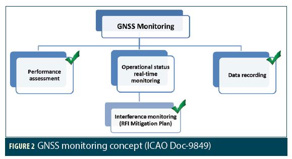
Therefore, the GNSS monitoring concept, as reported in the ICAO GNSS Manual (again, please see Additional Resources), covers the following use cases, see Figure 2.
1. GNSS performance assessment is a periodic off-line activity aimed at demonstrating the signal-in-space (SiS) conformance to ICAO Annex 10 relevant requirements (see Additional Resources).
2. GNSS operational status monitoring provides real-time information to technical staff and ATC services on the current operational status of GNSS services. RF interference (RFI) monitoring is typically part of this activity and monitors the GNSS spectrum providing timely warnings in case of potentially critical RFIs.
3. GNSS data recording is a legal recording service of GNSS data for post-incident/accident investigations.
In the framework of the BLUEGNSS project, the GNSS monitoring concept is a leading aspect that paved the way to the deployment of an innovative, multi-source monitoring network able to:
• assess and record GNSS performance, measurements, and data,
• analyze and report any detected RF interference (RFI) within the GNSS spectrum.
It is worth noting that ESSP is the EGNOS Service Provider for the period 2014-2021. Therefore, it is in charge of operations for the ground and space segments, overall infrastructure maintenance, and compliance with safety standards. Conversely, BLUEGNSS plays a different role: its network is mainly focused on the analysis of GNSS performance and its compliance to ICAO standards. Therefore, it is provided with additional monitoring elements in the BLUE-MED area that allow for accomplishing this goal.
More details on network architecture are provided in the next sections.
BLUEGNSS Monitoring Network: General Overview
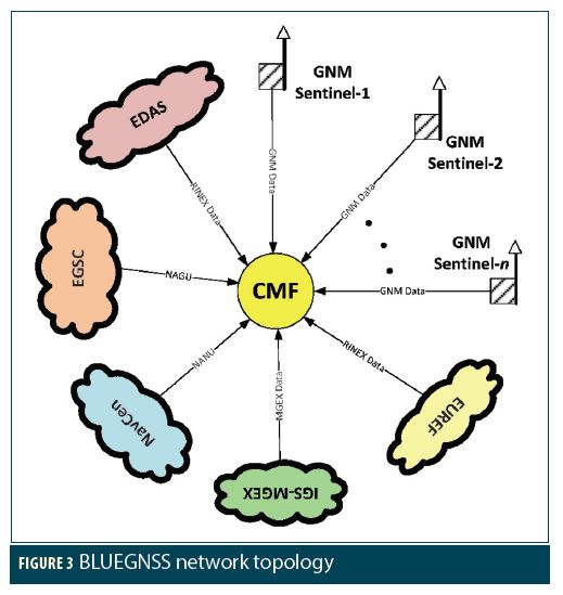
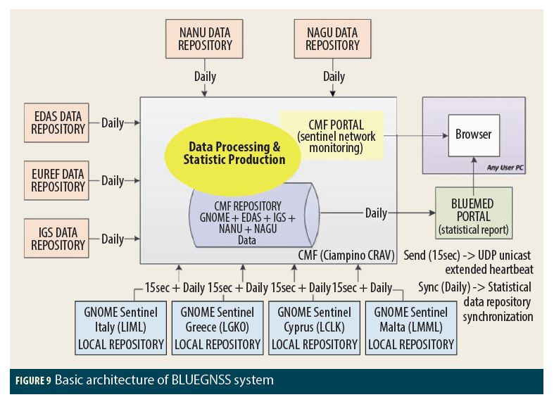
The BLUEGNSS monitoring network provides a common service of GPS, GPS/EGNOS, and Galileo performance assessment within the BLUE-MED area. A schematic picture of network topology is reported in Figure 3. It shows a TCP/IP star-network that connects some dedicated monitoring stations (developed by IDS and referred to as GNSS Operative Monitoring Equipment (GNOME) sentinels) to a common collector indicated with the acronym CMF (Central Monitoring Facility). This unit is also fed by data coming from other external, already existing GNSS networks and services, i.e., EDAS, IGS/MGEX, EUREF, NavCen, and EGSC.
This architectural choice is justified by the need to develop a flexible, scalable, and easily configurable network able to integrate and process data coming from several monitoring stations, even if they belong to independent networks. In this way, it is possible to increase the number of monitoring points within the BLUE-MED FAB without new installations, thus reducing costs and improving the service performance.
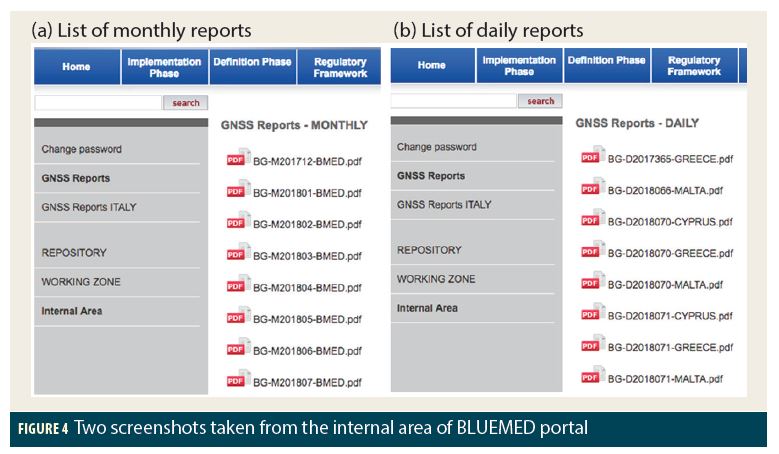
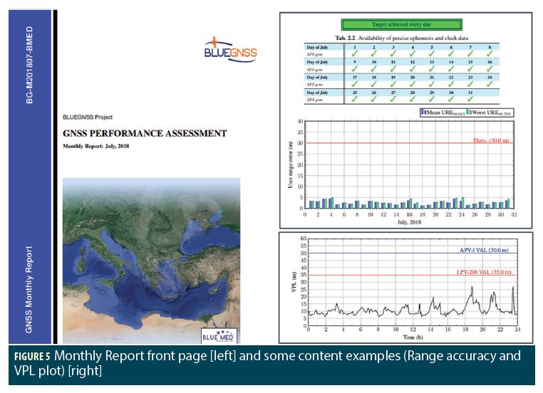
CMF outcomes and statistics are summarized in ad-hoc daily and monthly reports that are automatically produced and uploaded within a restricted internal area of the BLUE-MED portal (see Additional Resources and Figures 4 and 5). Thus, only authorized personnel, provided with a login and password, can download them.
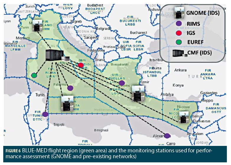
A geographic representation of the BLUE-MED flight region (bounded by a red line) is reported in Figure 6. This picture shows: (i) the location of GNOME sentinels (GNM labeled) belonging to the BLUEGNSS network and (ii) the positions of other external operative monitoring stations (green circles) that are approximately installed in the same region. It is worth noting that some of them (such as CNT, DJA, ATH, ALY) are very close or within the BLUE-MED FAB. Therefore, they can be effectively considered as further monitoring points to be connected to the BLUEGNSS network.
BLUEGNSS Sentinels
As previously stated, the GNSS monitoring stations (referred to as GNOME sentinels, see V. Pellegrini et alia) developed by IDS are the key elements of the BLUEGNSS network. Simply speaking, such units are designed to receive positioning signals and process them in order to:
• check the integrity of GNSS signals (e.g., in terms of carrier-to-noise ratio, pseudorange errors, etc.)
• produce statistical metrics able to characterize the GNSS performance in-situ (e.g., position accuracy, xDOP, number of used satellites, protection levels, etc.)
• monitor RF spectrum and detect possible intentional/unintentional interferences
• analyze the physical (PHY) and navigation (NAV) layers of positioning signals and record data and related metrics (according to relevant standards, see Additional Resources)
• investigate the cause of possible anomalies detected in-situ.
Such features make sentinels able to accomplish the following tasks as recommended by ICAO (see the monitoring concept schema shown in Figure 2 and Additional Resources):
• real-time monitoring of GNSS integrity to provide timely alert in case of detected anomalies
• post incident/accident investigation, yielding data logging and review capabilities
• GNSS ground validation campaigns, aimed at characterizing GNSS site performance (e.g., for GBAS and RIMS siting).
As mentioned, in the framework of BLUEGNSS, the main target is the development of a network able to carry out the global assessment of GNSS performance within BLUE-MED FAB. Therefore, in this context, BLUEGNSS sentinels have the important task of:
• computing some preliminary metrics from PHY and NAV layers
• sending the achieved outcomes to the CMF for the final processing and report publication.
In this context four stations have been deployed and installed within the following airports (see Figure 6).
• Kos Airport, Greece
• Luqa Airport, Malta
• Larnaca Airport, Cyprus
• Linate Airport, Italy.
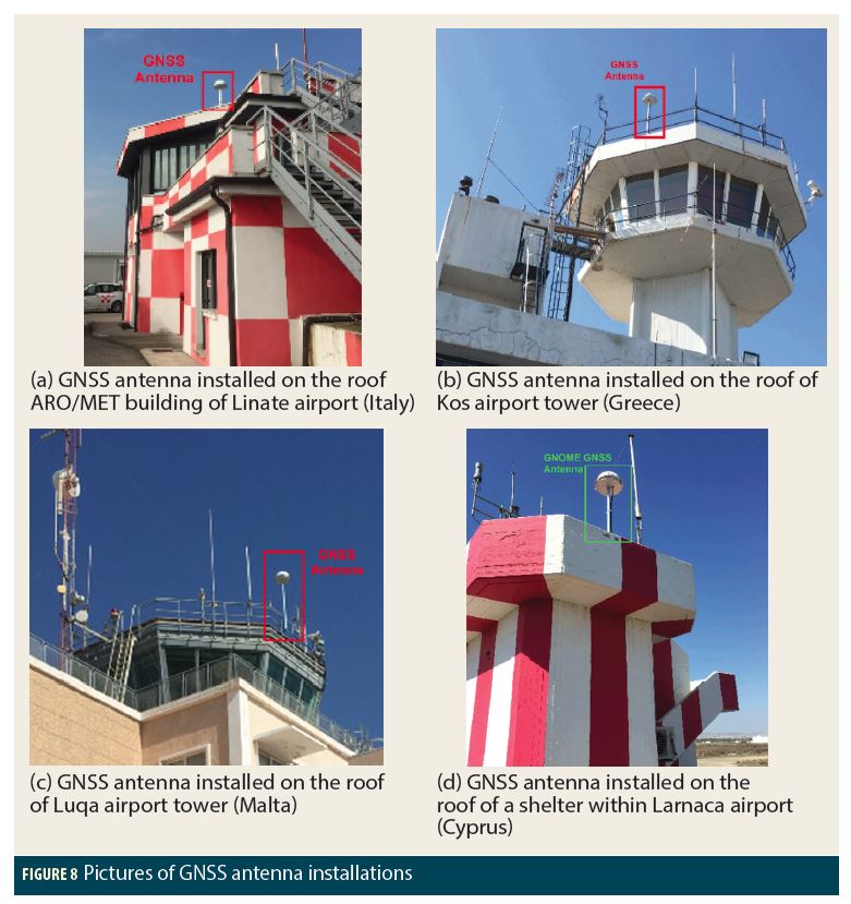
It is worth noting that, within each airport, the installation site has been carefully chosen in order to minimize the detrimental effects of possible local factors on the reception of positioning signals (e.g., masking effects due to orography or man-made obstacles, presence of transmitters, sources of multipath, etc.). Proper choice of site is essential for accomplishing reliable GNSS performance assessment.
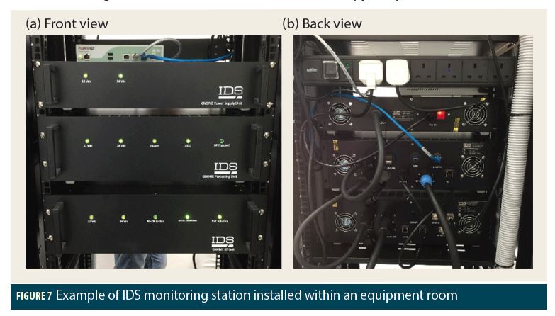
Each station is made up of the following units.
• Nr. 3 rackmount chassis (i.e., a power supply unit, a processing unit, and an RF and navigation unit); typically installed within a preselected equipment room (see Figure 7).
• Nr. 1 choke-ring multi-frequency GNSS antenna for multipath mitigation; typically installed on the roof of the building hosting the equipment (see Figure 8).
The communication between sentinel segment and CMF is achieved via Ethernet; properly configured hardware firewalls allow for safeguarding the integrity of this connection.
Additional External Resources
As mentioned earlier, the BLUEGNSS monitoring service is enriched by the data coming from external, already existing GNSS networks and services. A brief overview is reported in the following list. Please see Additional Resources for more information.
• EDAS provides GNSS performance metrics measured by the EGNOS RIMS. RIMS stations are distributed around the world, but it is worth noting that the European region has the highest density of such stations and, more importantly, some of them are placed within or very close to the BLUE-MED area (e.g., ROM-Ciampino, ATH-Athens, etc.). Thus, the inclusion of such stations has the advantage of increasing the number of monitoring points in the Mediterranean area, without additional installations.
• IGS-MGEX is a dense network of monitoring stations that offer the following services:
– An archive of precise GNSS orbital parameters that can be used by the CMF for the computation of some global metrics (such as GPS URE and Galileo SISE).
– Each station provides sets of RINEX data, which can be used to produce analysis of local GNSS performance.
• EUREF is a permanent GNSS network consisting of:
– continuously operating GNSS reference stations
– data centers providing access to the station data
– analysis centers that routinely analyze the GNSS data
– product centers or coordinators that generate the EPN products
– a Central Bureau that is responsible for the daily monitoring and management of the EPN.
This network has been included within the BLUEGNSS network to have access to RINEX data provided by those monitoring stations which are within or close to the BLUE-MED FAB.
• The NavCen (Navigation Center) server provides access to GPS NANUs, almanacs, and current operational advisories. Specifically, NANUs are used to assess the GPS continuity in compliance with ICAO Doc-9848 and RT/2016/028 (see Additional Resources).
• The EGSC (European GNSS Service Center) server provides access to Galileo NAGUs and almanacs. Specifically, NAGUs are used to assess the Galileo continuity in compliance with ICAO Doc-9848 and RT/2016/028 (see Additional Resources).
Central Monitoring Facility (CMF)
Simply speaking, the CMF operates as a central server whose role is collecting, recording, and processing data coming from each node of the BLUEGNSS network in order to produce key performance indicators (KPIs) for:
• a global GNSS performance assessment within the BLUE-MED area
• a local GNSS performance assessment of each site hosting a GNOME sentinel.
A pictorial representation of this unit is reported in Figure 9. This schematic highlights the main functional blocks of data gathering, processing, and storing assigned to the CMF. All computed KPIs are summarized within periodic reports (daily and monthly) that are uploaded within the BLUE-MED portal where they are available for consulting by authorized personnel.
The CMF unit is installed at the airport of Ciampino, within the ENAV/ACC (Area Control Center) facility.
Key Performance Indicators and Periodic Reports
All data collected by the CMF unit are used to produce daily and monthly reports on GPS, GPS/EGNOS, and Galileo performance for the following purposes.
From ICAO Doc-9849
7.8.3.1 – GNSS performance assessment may be used by States in order to:
a) periodically verify the performance of signals that have already been declared operational (such as GPS L1 and GLONASS L1); and/or
b) collect statistical data on technical elements to support decisions for operational approvals in a particular airspace based on new GNSS signals and/or constellations (such as GPS L5, GLONASS L3, BDS and Galileo).
Specifically, the declared objective of monthly reports is a periodic compliance analysis of the following services:
• GPS SPS (Standard Positioning Service)
• GPS/EGNOS APV-I and LPV-200
• Galileo OS (Open Service)
to ICAO requirements (noted earlier and in the Additional Resources) within the BLUE-MED FAB.
Conversely, daily reports aim at providing a local characterization of the aforementioned positioning services on an hour-by-hour basis. Therefore, their results are more detailed and very useful for the investigation of any detected anomaly.
According to ICAO, two different sets of key performance indicators (KPIs) are used to characterize the service provided by GNSS core constellations in stand-alone mode (e.g., GPS-only and Galileo-only) or augmented by SBAS systems (e.g., GPS/EGNOS). The following subsections provide an overview of these KPIs, including a description of the RFI monitoring implemented by the BLUEGNSS sentinels.
Performance Parameters of Core Positioning Systems (GPS and Galileo)
Per ICAO, a list of core constellation performance parameters suitable for periodic verification is reported in Table 1. Such parameters are focused on GPS, but they can be also extended to other constellations, such as Galileo, even if the related SARPs are not available yet.
GPS.KPI-1: Range Domain Accuracy
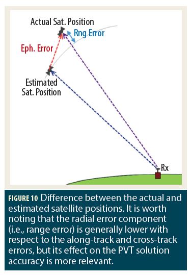
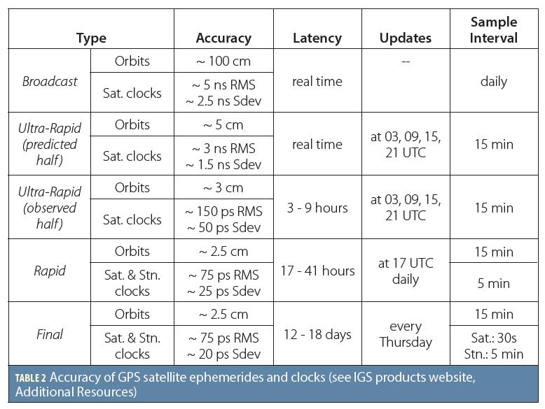
The range domain accuracy is an indication of the SiS user range error (URE) dispersion that describes the statistical uncertainty of the modeled pseudorange due to errors in the broadcast orbit and clock information (O. Montenbruck et alia). It is well known that broadcast ephemerides are used by GNSS receivers to assess the position of GPS satellites. Such estimations are typically affected by errors of some meters (see Table 2) and could degrade the receiver position computation. Figure 10 shows the difference between the estimated and actual satellite position.
It is worth noting that the main contributions of the URE metric are ephemeris and clock errors, because antenna variations and signal imperfections are usually at the centimeter or millimeter level (see Additional Resources). Therefore, the instantaneous URE for a user at the location u can be computed as shown in Eq. (1), where s and b are respectively the actual satellite position and clock bias, sʹ is the satellite position derived from broadcast ephemerides, bʹ is the broadcast satellite clock bias, · is the vector dot product, and ||·|| is the norm operator.
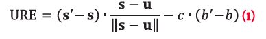
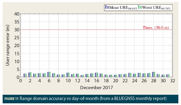
Figure 11 shows an example of a range domain accuracy plot in which the mean and worst URE are always below the ICAO threshold.
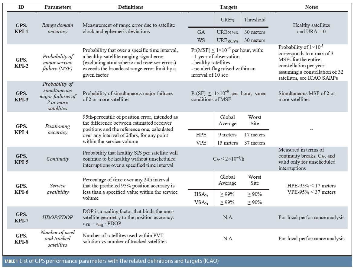
GPS.KPI-2: Probability of Major Service Failure
From ICAO SARPs
§3.7.3.1.4 – Probability of major service failure. The probability that the user range error (URE) of any satellite will exceed 4.42 times the upper bound on the user range accuracy (URA) broadcast by that satellite without an alert received at the user receiver antenna within 10 seconds shall not exceed 1×10⁻⁵ per hour.
Att. D §4.1.6 – A major service failure is defined to be a condition over a time interval during which a healthy GPS satellite’s ranging signal error (excluding atmospheric and receiver errors) exceeds the range error limit of 4.42 times the upper bound on the user range accuracy (URA) broadcast by a satellite for longer than the allowable time to alert (10 seconds). The probability of 1×10⁻⁵ in Chapter 3, 3.7.3.1.4 corresponds to a maximum of 3 major service failures for the entire constellation per year assuming a maximum constellation of 32 satellites.
From the definition reported in the ICAO SARPs ATT-D §4.1.6, the probability of major service failure (MSF), can be formulated as shown in Eq. (2).

where for any received satellites belonging to GPS constellation and one year of observation (ICAO Doc-9849). The alert flag is provided by the GPS NAV message in the HOW word (see GPS Interface Control Document in Additional Resources).
In compliance with the previous definitions, the computation of this metric requires an observation period of one year (leap year equals 366 days), during which the number of MSF, namely NMSF, shall be counted by taking into account all aforementioned constraints (see the above C-condition). When the NMSF parameter is available, it is possible to calculate by using Eq. (3) (which is a possible practical implementation of Eq. (2)).
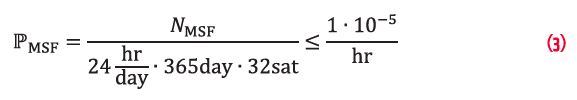
As stated in ATT-D §4.1.6 of ICAO SARPs, the MSF computation requires an observation period of one year. Therefore, a monthly analysis is too short a period for the computation of to be directly compared to the ICAO threshold of 1 × 10⁻⁵ per hour. As a consequence, a monthly analysis can only provide the number of occurred MSF events, while the computation of their probability shall be postponed until the end of the year.
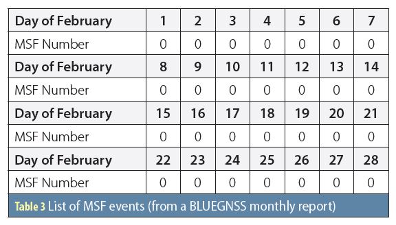
Table 3 proposes an example of a day-by-day list containing the number of detected MSFs. Within the period of interest, no anomaly was detected.
GPS.KPI-3: Probability of Simultaneous Major Failures of 2 or More Satellites
The probability of simultaneous major failure (SF) of two or more satellites, , is similar to , with the main difference that the number of involved satellites shall be greater or equal to two. Thus, the theoretical formulation is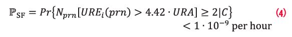
with for any received satellite and Nprn[.] indicates the number of satellites that satisfy the condition within the square brackets.
Like the previous the computation of this metric requires a very long observation period (≥ 1 year), during which the number of simultaneous major failures, namely NSF, shall be counted by taking into account the aforementioned constraints (see the above C-condition). If the NSF parameter is known, it is possible to calculate as follows: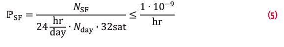
where Nday is the number of days of the observation period. Therefore, a monthly analysis can only provide the number of SF occurring within the period of interest.
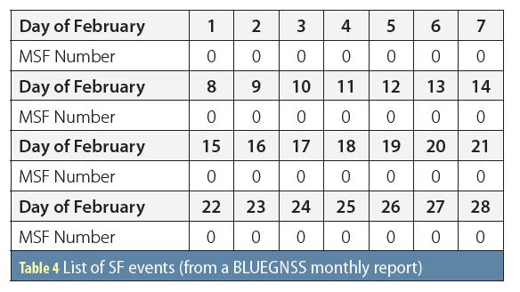
Table 4 provides an example of a day-by-day list containing the number of detected SFs. Within the period of interest, no anomaly was detected.
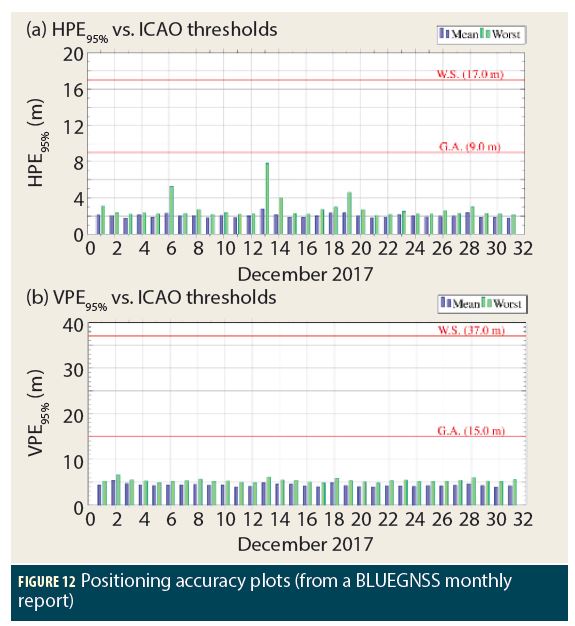
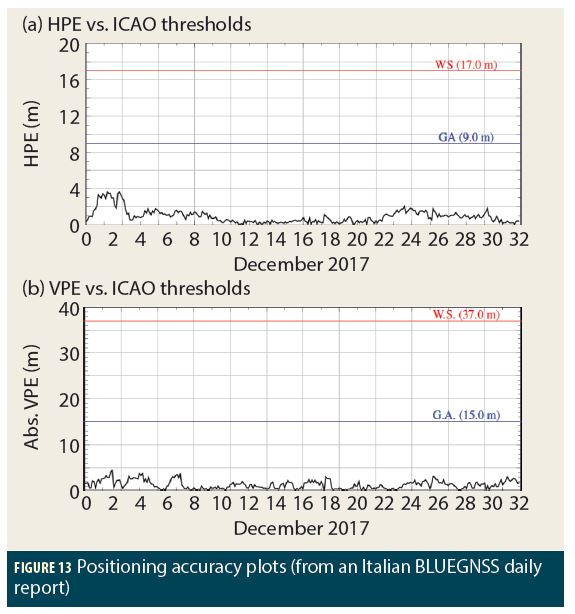
GPS.KPI-4: Positioning Accuracy
Positioning accuracy is an indication of the position error dispersion, computed as the difference between the position assessed by a representative GPS receiver (in compliance with ICAO SARPs APP-B §3.1.3.1.1) and that of a geo-referenced one. Furthermore, the GPS SPS position errors shall not exceed the following limits (again from ICAO SARPs, §3.7.3.1.1.1).
• Horizontal position error (HPE): 9 m (global average 95% of the time); 17 meters (worst site 95% of the time)
• Vertical position error (VPE): 15 m (global average 95% of the time); 37 meters (worst site 95% of the time)
Therefore, the positioning accuracy (in meters) is typically referred to as the 95-percentile computed as follows.
where:
• i indicates the i-th epoch related to the i-th position provided by the representative GPS receiver
• is the probability
• is the horizontal positioning accuracy
• is the vertical positioning accuracy.
The procedure to check the above requirements is briefly illustrated below.
• The average positioning accuracy is compared to the global average target. Thus, assuming M monitoring stations (placed in M different locations), each one able to provide a measurement of GPS accuracy (i.e., a pair per every j-th station), it is possible to compute the average accuracy as follows.
• The worst positioning accuracy is compared to the worst location target. Thus, assuming M monitoring stations, each one provided with a pair of (), the worst accuracy is calculated as follows
Figure 12 and Figure 13 show an example of positioning accuracy plots in which the ICAO thresholds are never violated within the periods of interest.
GPS.KPI-5: Continuity
Continuity is the probability that the healthy SIS per satellite will continue to be healthy without unscheduled interruptions over a specified time interval.
As indicated in Table 1, this metric is generally computed in terms of continuity breaks. Thus, this KPI becomes the probability of losing the SIS availability due to unscheduled interruptions.
A continuity break event at the i-th epoch, namely ECB[prn, i], of the prn GPS satellite occurs only if the following condition is true:
where [H(prn)]i is the health status (GPS Interface Control Document) at the i-th epoch and !(.) is the not operator. Thus, the probability of continuity breaks can be computed as follows:
where NCB is the number of continuity break events within the observation time (i.e., T = Nday . 24 hr/day, where Nday is the number of days) and for each prn belonging to a constellation of 32 GPS satellites.
Table 5 reports the number of continuity breaks per day within the period of interest. No anomaly was detected.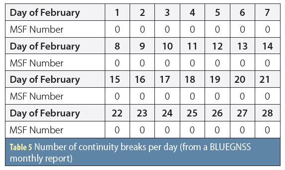
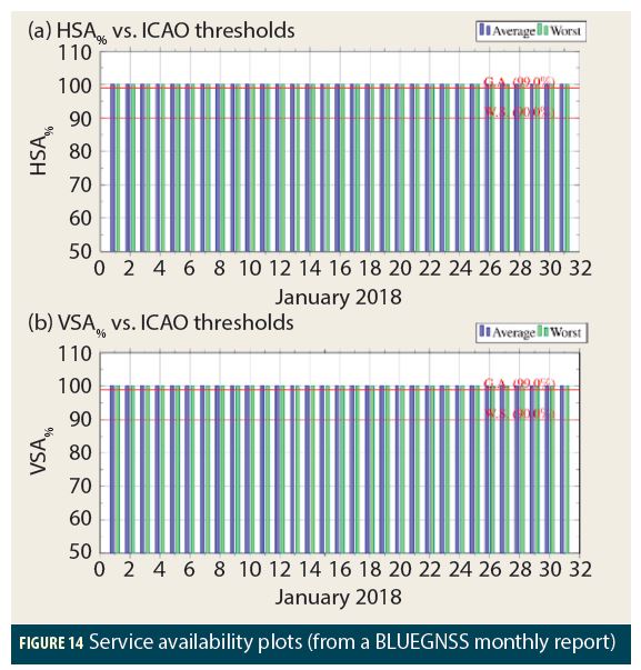
GPS.KPI-6: Service Availability
The GPS horizontal or vertical positioning service, within the generic interval T = [τ, τ + Δ], is available (or equivalently the availability flag = true) only if the 95% horizontal or vertical position error (respectively HPE95% and VPE95%), computed within the T-interval, is respectively lower than 17 meters or 37 meters.
Thus, both the horizontal and vertical service availabilities (respectively indicated with the acronyms: HSA% or VSA%) are defined as the percentage of true availability flags calculated within a daily interval of 24 hours.
In compliance with ICAO, this metric should satisfy the following targets.
• HSA% ≥ 99% horizontal service availability, average location (17 meters, 95% threshold).
• VSA% ≥ 99% vertical service availability, average location (37 meters, 95% threshold).
• HSA% ≥ 90% horizontal service availability, worst-case location (17 meters, 95% threshold).
• VSA% ≥ 90% vertical service availability, worst-case location (37 meters, 95% threshold).
Figure 14 provides an example of HSA and VSA plots achieved by setting the Δ-parameter equal to zero.
In this way, the sliding window is collapsed to a sample and, consequently, the availability flag is computed for each HPE and VPE sample. Both plots show that the service availability is always > 99%.
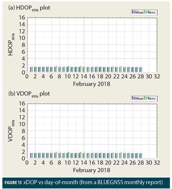
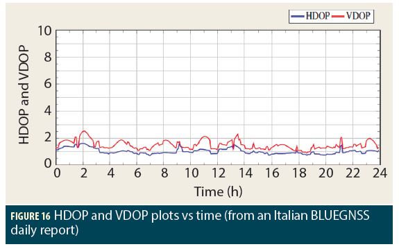
GPS.KPI-7: HDOP/VDOP
Dilution of precision (DOP) is a scaling factor, that binds the user-satellite geometry to the position accuracy, see Eq. 11.
where σrng and σxPE are respectively the range and position error standard deviations. Specifically, xPE stands for horizontal and vertical position errors (respectively HPE and VPE) and consequently xDOP indicates respectively the horizontal (H) and vertical (V) DOPs.
Roughly speaking, DOP indicates the quality of user-satellite geometry. Therefore, according to Eq. (11), low DOPs indicate favorable geometries and, consequently, low position errors, and vice versa implies worse accuracies. More details on this metric are available in Additional Resources (E. D. Kaplan and C. J. Hegarty; P. Misra et alia).
Figure 15 and Figure 16, respectively, propose some examples of monthly and daily xDOP plots.
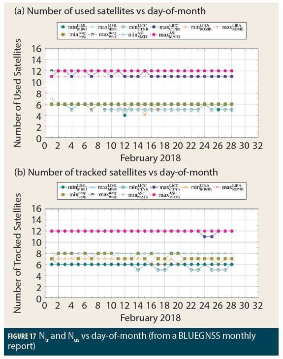
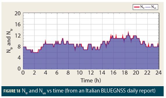
GPS.KPI-8: Number of Used and Tracked Satellites
The number of used and tracked satellites is another useful metric for investigating the causes of poor position accuracies. Indeed the case of only a few tracked satellites is an indication of an anomaly that affects the reception of positioning signals. This is caused for example by possible interfering signals, masking effects, hardware damages, etc. At the same time, the number of satellites used allows us to shift the attention to the PVT solution and the motivations for possible satellite exclusions.
Figure 17 and Figure 18, respectively, propose some examples of monthly and daily Ntr (number of tracked satellites) and Nus (number of used satellites) satellites plots.
GPS/EGNOS Performance Parameters
According to ICAO, a list of GPS/EGNOS performance parameters suitable for periodic verification is reported in Table 6.
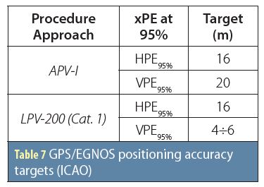
GPS-EGNOS.KPI-1: Positioning Accuracy
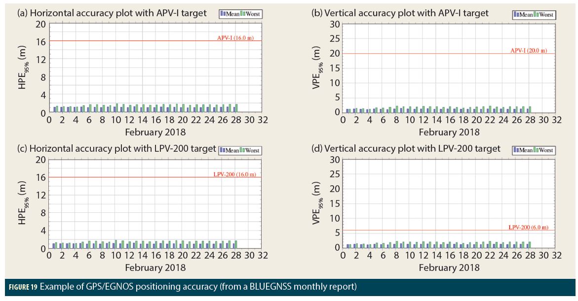
Positioning accuracy is an indication of the position error dispersion and is defined as 95th-percentile of horizontal and vertical position errors (H/VPEs). The related targets in the case of GPS/EGNOS APV-I and LPV-200 positioning service are summarized in Table 7.
Output typology is similar to the GPS positioning accuracy. Figure 19 shows some examples in which the ICAO APV-I and LPV-200 thresholds are never violated within the month of interest.
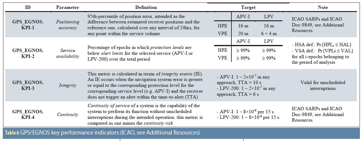
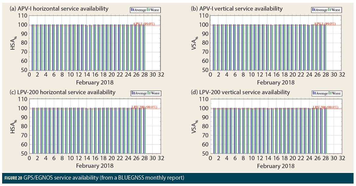
GPS-EGNOS.KPI-2: Service Availability
The percentage of service availability (xSA, where x can be H in the case of horizontal or V in case of vertical) is assessed by computing the following daily probabilities:
where H/VPLi are respectively the horizontal/vertical protection levels at the i-th epoch and H/VAL are respectively the horizontal/vertical alert limit derived from the ICAO SARPs, i.e., APV-I: HAL = 40 meters and VAL = 50 meters, LPV-200: HAL = 40 meters and VAL = 35 meters.
Figure 20 shows an example of GPS/EGNOS service availability plots against the ICAO APV-I and LPV-200 thresholds. Specifically, all graphs report a service availability level that is always > 99%.
GPS-EGNOS.KPI-3: Integrity
Integrity
Integrity is a measure of the trust that can be placed in the correctness of the information supplied by the total system. Integrity includes the ability of a system to provide timely and valid warnings to the user (alerts) when the system must not be used for the intended operation (or phase of flight).
In other words, the integrity includes the ability of a system to provide timely warning (an alert) to users when the system itself cannot be used to carry out the desired procedure (I. Konaktchiev and C. Butzmuehlen).
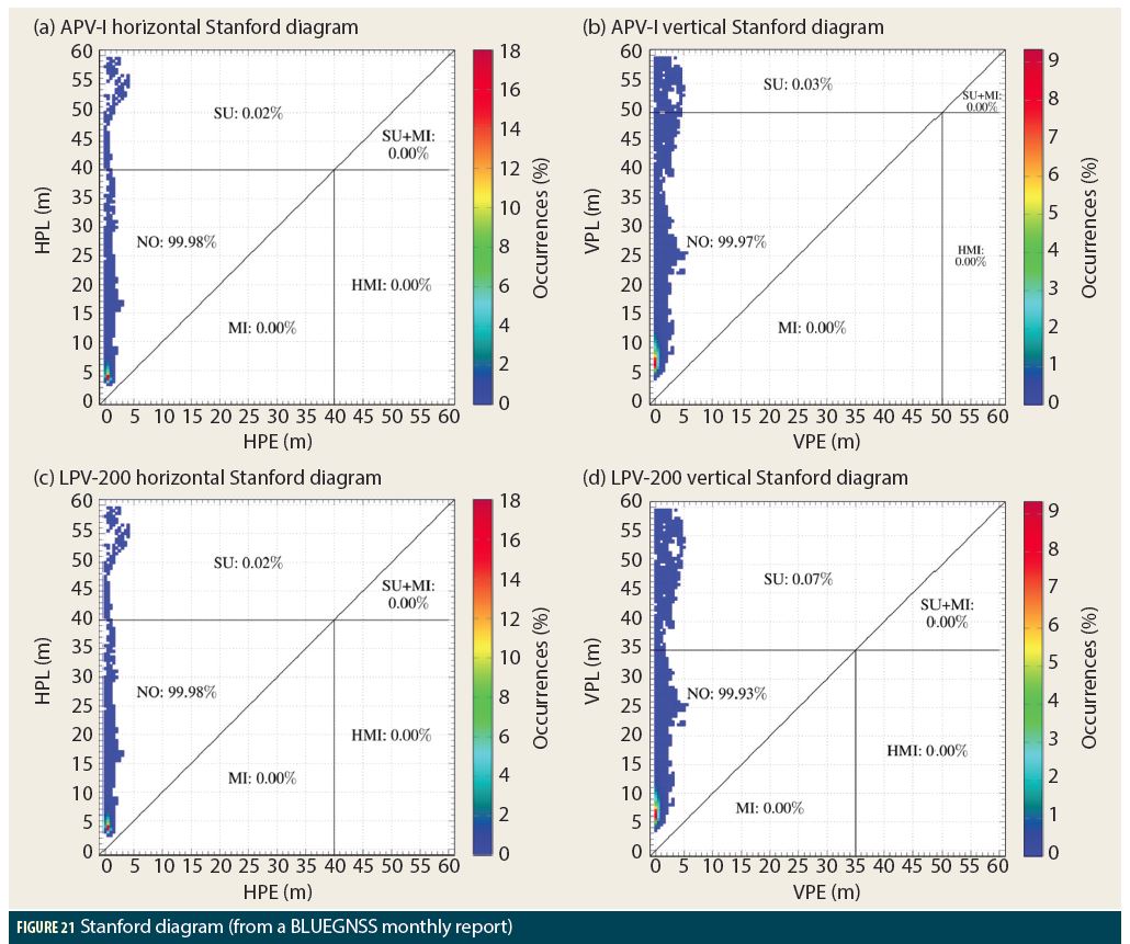
An APV-I or LPV-200 integrity event (IE) occurs when the navigation system error is greater than or equal to the corresponding protection level for APV-I or LPV-200 and no alert is emitted within the time-to-alert (TTA) period (ICAO).
Position domain safety index (xSI, x = H, horizontal, or V, vertical) is defined as the ratio between xPE and the related xPL at the i-th epoch, i.e., xSIi = xPEi/xPLi.
• If xSI < 1, no anomaly occurred, i.e., normal operation (NO), xPL < xAL. or system unavailable (SU), xPL ≥ xAL.
• Conversely, xSI ≥ 1 indicates misleading information (MI), xPE < xAL, or worse hazardous misleading information (HMI), xPE ≥ xAL.
According to the previous definitions, the probability of IE can be computed as shown in Eq. (12) and the related targets are shown in Table 7.
Stanford diagrams are the typical tool used to analyze the integrity (see Additional Resources). Such plots are built by gathering data (i.e., xPL vs xPE) from all monitoring stations for the entire observation period (i.e., one month). Some examples are shown in Figure 21.
GPS-EGNOS.KPI-4: Continuity of Service
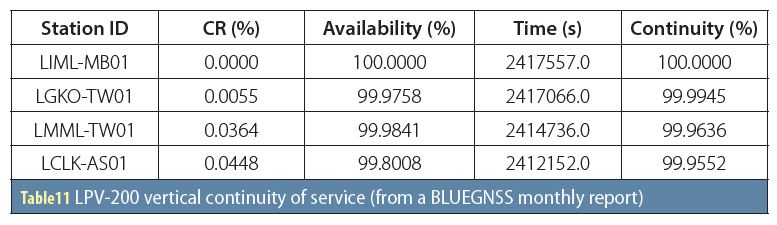
The continuity of service of a system is the capability of the system to perform its function without unscheduled interruptions during the intended operation (ICAO). According to ICAO Doc-9849, this metric is computed as one minus the continuity risk.
The continuity risk (CR) is defined as the ratio between the total number of continuity events using a time-sliding window of 15 seconds, and the number of samples with valid and available APV-I or LPV-200 solutions.
A single continuity event (CE) occurs if the system is available at the start of the intended operation and it becomes not available within the next 15 seconds. Such performance shall be obtained under fault-free conditions.
Table 8 lists the continuity of service targets coming from our two ICAO documents, i.e., 1 – 8 × 10⁻⁶ per 15 seconds for both the APV-I and LPV-200 procedures. Furthermore, according to the statement reported in App. G, §2.6 of ICAO Doc-9849, an acceptable observation period for this kind of analysis shall be larger than 22 days, e.g., at least one month.
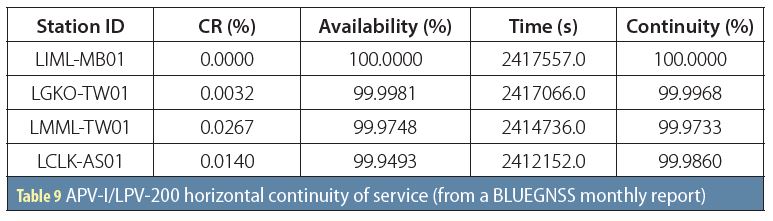
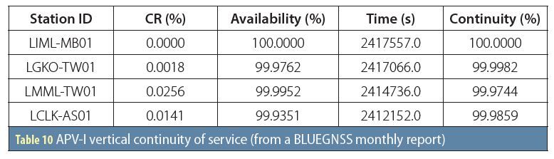
The procedure adopted to compute the continuity of service is illustrated within App. G of ICAO Doc-9849. This kind of analysis is carried out for every GNSS monitoring station within an observation period of one month and Tables 9 to 11 provide a set of typical outcomes.
RF Interference Analysis
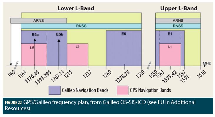
In the framework of the BLUEGNSS project, E5/L5, L2, and E1/L1 frequencies are watched over by every BLUEGNSS monitoring sentinel in order to detect the presence of possible RF interference, which might degrade either GPS or Galileo performance. This task is accomplished by partitioning the spectrum shown in Figure 22 into the following three frequency ranges, which are continuously monitored.
• E5/L5 frequency range – Central frequency at 1185.00 MHz with a bandwidth of 50 MHz
• L2 frequency. range – Central frequency at 1227.60 MHz with a bandwidth of 50 MHz
• L1/E1 frequency. range – Central frequency at 1575.42 MHz with a bandwidth of 50 MHz
By adopting a conservative approach, any interfering signal that crosses the interference mask (provided by either ICAO SARPs or the ESA technical report (J. Samson)) is considered potentially dangerous for the GNSS integrity and, consequently, such events shall be logged and reported to authorized personnel.
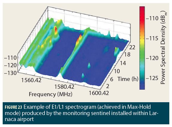
Figure 23 proposes an E1/L1 spectrogram generated by the BLUEGNSS sentinel installed within the airport of Larnaca. This picture shows the presence of an anomalous RF interference at the L1 frequency that caused a temporary loss of GPS signal with a consequent degradation of GPS and GPS/EGNOS service performance. This anomaly can be noted in the spectrogram of Figure 23, corresponding to the central frequency and in the time slot of 16.00÷18.00. Indeed, an increase of power density of ~10dB (red peaks) is visible. Such interfering events were also confirmed by pilot reports on GPS loss in the Nicosia FIR within the period March-April 2018.
Achieved Results and Conclusions
The following list contains a brief summary of the most significant results achieved at the end of the BLUEGNSS project.
• BLUEGNSS monitoring network is fully operative 24/7.
• Reports are available (to registered users) on BLUE-MED website (http://www.bluemed.aero/).
• GNSS Italian reports were used as Performance Assessment Reference by Italian CAA (ENAC) to approve GPS-based procedures without any additional mitigation (ENAC letter of March 16, 2018, No. ENAC-VDG-16/03/2018-0028476-P).
• Interference events detected by Kos and Larnaca GNOME sentinels were confirmed by pilot reports on GPS loss in the Nicosia FIR during some days in March and April 2018 (see the following links):
– European Parliament: http://www.europarl.europa.eu/sides/getDoc.do?type=WQ&reference=E-2018-001794&language=EN;
– European Commission answer http://www.europarl.europa.eu/sides/getAllAnswers.do?reference=E-2018-001794&language=EN;
– Cyprus information channel: http://en.cyplive.com/ru/news/k-vostoku-ot-kipra-samolety-nachali-teryat-gps-signal.html.
In conclusion, BLUEGNSS is the first project of its kind to be coordinated at the FAB level. It may serve as a catalyst to spread RNP APCH know-how in the region and beyond, to the whole of Europe.
Acknowledgments
The authors wish to thank the entire team of DCAC, HCAA, MATS, ENAV, GSA, EC, and IDS that actively collaborated for the success of each phase of the BLUEGNSS project. The author’s are also grateful for funding from the European GNSS Agency under the European Union’s Horizon 2020 research and innovation program under grant agreement No. 687198.
Additional Resources
1. BLUE MED Portal: http://www.bluemed.aero/nodo.php?id=326
2. EDAS link: http://www.gsa.europa.eu/egnos/edas/technical-information
3. EGSC link: http://www.gsc-europa.eu/system-status/orbital-and-technical-parameters
4. EU, European GNSS (Galileo) Open service, SIS ICD, Issue: 1.2, November 2015
5. EUREF link: http://www.epncb.oma.be/
6. European GSA, EGNOS Data Access Service (EDAS), Service Definition Document, Issue: 2.1, December 2014
7. GPS Interface Control Document, IS-GPS-200F
8. ICAO, Annex 10, Vol.1, Amend. 89 (13 Nov. 2014), Aeronautical Telecommunications – Radio Navigation Aids, 6th Ed., 2006
9. ICAO Doc-9849, Global Navigation Satellite System (GNSS) Manual, 3rd Ed., 2017
10. IGS-MGEX link: http://mgex.igs.org/
11. IGS products link: http://www.igs.org/products
12. Kaplan, E. D. and Hegarty, C. J., Understanding GPS – Principle and Application, Artech House, 2nd Ed., 2006
13. Konaktchiev, I. and Butzmuehlen, C., “APV WG/EGNOS SIS Validation Sub-group – Agenda Item 4: First Glance Algorithm Description,” Eurocontrol, 2nd meeting, October 2005
14. Misra, P., Burke, B. P., and Pratt, M. M., “GPS Performance in Navigation,” Proceedings of the IEEE, Volume: 87, Issue: 1, January 1999
15. Montenbruck, O., Steigenberger, P., and Hauschild, A., “Broadcast versus Precise Ephemerides: A Multi-GNSS Perspective,” GPS Solutions, Volume: 19, Issue: 2, April 2015
16. Pellegrini, V., Principe, F., Tomei, A., Mori, M., Natali, M., and Cioni, R., “The GNSS Operative Monitoring Equipment (GNOME): An SDR-Based Solution for Integrity Assurance,” Proceedings of NAVITEC 2012, ESTEC Noordwijk (The Netherlands), December 2012
17. Phelts, R. E., Gao, G. X., Wong, G., Heng, L., Walter, T., Enge, P., Erker, S., Thoelert, S., and Meurer, M., “Aviation Grade – New GPS Signals, Chips Off the Block IIF,” Inside GNSS, July 2010
18. RT/2016/028, BLUEGNSS Project – D810.1: GNSS Performance and Interference Assessment Parameters Study Report, IDS Ingegneria Dei Sistemi S.p.A.
19. Samson, J., “EGNOS v. 3 site RF requirements,” Technical Report ESA-DTEN-NF-TN/03441, ESA, September 2015
20. Schmid, R., Rothacher, M., Thaller, D., and Steigenberger, P., “Absolute Phase Center Corrections of Satellite and Receiver Antennas,” GPS Solutions, Volume: 9, Issue: 4, November 2005
21. US Nav. Cen. link: http://www.navcen.uscg.gov/?pageName=gpsAlmanacs
22. Wong, G., Phelts, R. E., Walter, T., and Enge, P., “Characterization of Signal Deformations for GPS and WAAS Satellites,” Proceedings of the 23rd International Technical Meeting of the Satellite Division of The Institute of Navigation (ION GNSS 2010), Portland, OR, September 2010
Authors
Fabio Principe is a senior radio-navigation engineer at Communication, Navigation, and Surveillance (CNS) Laboratory of IDS, Ingegneria Dei Sistemi S.p.A. He received the Master Degree (cum Laude) in Telecommunications Engineering from the University of Pisa on May 2003 and the Ph.D. degree in Information Engineering, curriculum: Communication Systems, on May 2007. From 2004 to 2007, He also worked as consultant on GNSS projects promoted by ESA. He also spent 7 months at the Communication Sciences Institute, USC (Los Angeles CA, USA), working with Prof. Keith M. Chugg on iterative detection problems. His fields of interest are in the wide areas of communication systems, signal processing algorithms, satellite navigation systems, spread-spectrum techniques, modern coding theory, and Software-Defined Radio techniques.
Giuseppe Di Bitonto is a Project Manager at ATM and Airports department in Air Navigation Division of IDS Ingegneria dei Sistemi. He received B.S. and M.S. in Telecommunication Engineering from University of Rome “Tor Vergata”. He gained an extensive experience in experimental projects on the GNSS use for Air Navigation, specifically focused on PBN approach. In particular, he was involved in several activities related to GNSS signal performance assessment using both simulation platforms and measurement systems. He managed BLUEGNSS project on behalf of IDS.
Andrea Tomei is a senior IT Developer at Communication, Navigation and Surveillance (CNS) Laboratory of IDS, Ingegneria Dei Sistemi S.p.A. He graduated in 1996 as IT Specialist. He has an extensive experience in Radar and air-navigation console developments. Specifically, his interests are in the general area of SW architecture designs and development of real-time applications. Indeed, he was involved in experimental air-navigation projects requiring the development of airport simulators, aircraft tracking systems, and applications for helicopter IFR and VFR operations.
Patrizio Vanni is an aerospace engineer working for ENAV International Strategies Office and following main International fora on Aviation Satellite Navigation. He is permanent member of ICAO PBN Task Force, ICAO Navigation System Panel, Eurocontrol RAISG and Navigation Steering Group, Land and Take Off Group on GBAS, EGNOS MRD Change Control Board, EGNOS Security expert group and Galileo Reference Centre Working Group. He was graduated in 2003 in Aerospace Engineer and holds a master of science in “Advanced Communications and Navigation Satellite System”. He started following the EGNOS program on 2004 with the set-up of the Ciampino EGNOS Data Collection Station and supporting the Initial Operation Phase, then he joined Mission Control Centre Operations as Engineering Support and then as Product Assurance and Safety Responsible and RIMS manager.
Katerina Strelcova is an Aviation Market Development Innovation Officer at the European GNSS Agency (GSA) since 2014. She is driving a development of European Global navigation satellite system (EGNOS and Galileo) applications and new solutions on the market improving aviation safety and accessibility. In particular, she is managing the GSA grant program to foster EGNOS adoption in aviation, specific research and development projects, and the development of prototypes. Prior to joining the GSA, she has worked at GE Aviation on Safety Management System. She holds a Master degree in Air Traffic Control and Management from Prague and Master of Science in Civil Engineering from the University of Texas. She has supervised the BLUEGNSS project as a GSA Project Officer.


